![1 generation [2010 - 2015]](/uploads/Renault_Duster_2010-2015_.jpg)

Renault Duster camshaft condition
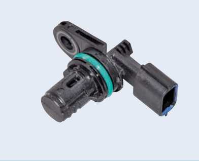
sensor The ECU uses the sensor signal to coordinate fuel injection processes in accordance with the order of operation of the cylinders and control the solenoid valve of the variable valve timing system. The sensor thesis is based on the Hall effect. To determine the condition of the piston of the 1st cylinder during the compression stroke, the sensor responds to the passage of the master disk located on the intake camshaft and provides the ECU with low-level voltage pulses.
To control the power of the engine on the car, an electronic throttle actuator is used. The driver, in accordance with his intentions to change the engine power, presses on the "gas" pedal. The state of the pedal is monitored by 2 angular displacement sensors (located in the “gas”
pedal module), the “gas” pedal module, which redistribute the ECU signals. From the ECU, the corresponding signals are sent to the throttle assembly control unit, which changes the state of the damper. In addition, commands are received from the ECU to change the ignition moment, the moment and duration of fuel injection. With this method of throttle control (to ensure the safety of movement and reduce fuel consumption), the ECU can regulate the state of the damper without changing the state of the “gas” pedal by the driver.
The Renault Duster accelerator pedal module uses 2 pedal status sensors to ensure the greatest safety. Both sensors are sliding contact potentiometers mounted on a common shaft. With each change in the state of the pedal, the resistance of the sensors changes and, relatively, the voltage that is transmitted to the ECU. In the absence of a signal from one of the sensors of the “gas pedal” module, the engine can initially operate only in idle mode. As soon as the control system recognizes the opposite pedal state sensor for a certain time, it will be possible to move the car.
In the absence of signals from both sensors of the state of the “gas” pedal, the engine can only function at increased idle cycles and does not respond to the “gas” pedal - only independent movement to the place of repair in 1-2
gears is permissible.
The throttle assembly control unit,
consisting of a continuous current motor with a gearbox and 2
damper status sensors, is attached to the throttle assembly housing.
The damper is unlocked and locked at the required angle by an electric motor (through a gearbox) of the throttle assembly control unit according to signals received from the computer.
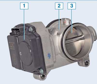
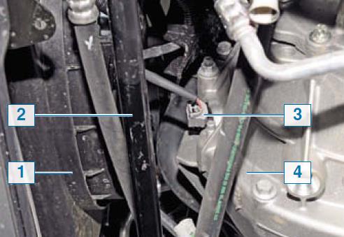
Throttle assembly of the car Renault Duster:
- 1 - control unit;
- 2 - base;
- 3 - throttle valve
When the electric motor is de-energized, the damper mechanically (with the help of a spring) moves to an emergency (somewhat ajar) state. 2 throttle angle sensors are predefined for feedback from the ECU. Both sensors are sliding contact potentiometers. The sliding contact of each sensor is fixed on the driven gear of the gearbox, which sits on the throttle shaft. The contacts touch the tracks of the potentiometers in the cover of the control box. When the state of the throttle valve changes, the resistances of the potentiometer tracks change and, thereby, the signal voltages that are transmitted to the computer. The electronic unit of the control system can distinguish the signals of one sensor from another and perform test functions. If the ECU receives an indistinguishable signal from one of the throttle position sensors or does not receive any signal at all, and the opposite sensor is operating normally, then under these conditions the car typically responds to a change in the state of the gas pedal. If the ECU receives indistinguishable signals from both angle sensors or does not receive any signals at all, then the power unit can only operate at high idling speed and does not respond to the gas pedal.
When the electric motor of the throttle assembly control unit is de-energized
or both damper status sensors fail, the engine
can only function at increased idling cycles
and does not respond to the
“gas” pedal - only independent movement to the
repair site in 1-2 gears is permissible.
The coolant temperature sensor is located in the thermostat housing located on the left edge of the cylinder head. The sensor rod is washed by the coolant coming out of the cylinder head cooling jacket.
The sensor is a negative temperature thermistor, i.e. its resistance decreases as the temperature rises. The ECU supplies a stabilized voltage to the sensor and, based on the voltage drop across the sensor, calculates the coolant temperature, the values of which are used to adjust the fuel flow and ignition timing. In the event of a breakdown in the sensor circuits, the ECU turns on the cooling system fan for a continuous operation schedule and calculates the temperature value using a bypass algorithm.
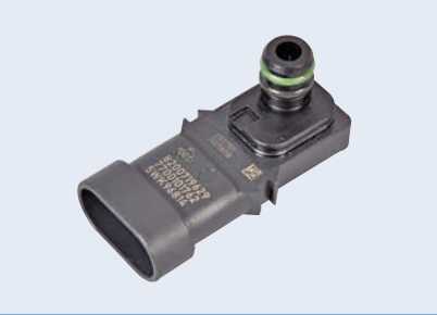
The absolute air pressure sensor of a Renault Duster car is located on the top right side of the engine air path receiver.
Renault Duster coolant temperature sensor
The sensor includes a receptive piezoelectric element and a load variable resistor. The ECU supplies a reference voltage of +5 V to the sensor resistor. The piezoelectric element of the sensor reacts to a change in pressure (vacuum) in the receiver and converts the reference voltage. This change in voltage is taken into account by the ECU when calculating the amount of air entering the power unit. The intake air temperature sensor is located on the top front of the receiver.
The sensor is a negative temperature thermistor, i.e. its resistance decreases as the temperature rises. The sensor changes its resistance depending on the air temperature at the inlet to the receiver. The information coming from the sensor is considered by the ECU when calculating the air consumption of the engine and for adjusting the ignition timing.
The knock sensor of a Renault Duster car is fixed on the front wall of the cylinder block between the 2nd and 3rd cylinders.
Air temperature sensor at the inlet of a Renault Duster car:
1 - engine 2.0;
2 - engines 1.6
The sensor responds to high-frequency oscillations of the cylinder block that occur during detonation combustion of fuel. The piezoceramic receptive component of the knock sensor generates an alternating voltage signal, the amplitude and frequency of which correspond to the vibration parameters of the cylinder block wall. When detonation occurs, the amplitude of vibrations of a certain frequency increases. At the same time, to suppress detonation, the ECU adjusts the ignition timing in the direction of a later one. The engine control system uses 2 oxygen concentration sensors - coordinating and diagnostic. The coordinating oxygen concentration sensor is located in the engine exhaust manifold. The oxygen concentration sensor is a galvanic current source, the output voltage of which depends on the oxygen concentration in the environment surrounding the sensor.
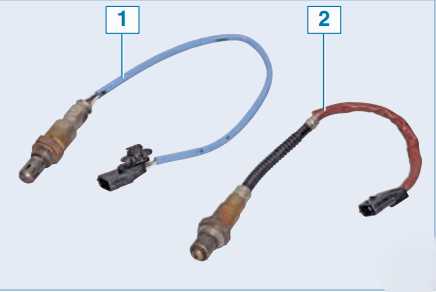
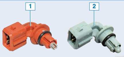
Renault Duster oxygen concentration sensors:
- 1 - coordinating;
- 2 - diagnostic
Based on the signal from the sensor about the presence of oxygen in the exhaust gases, the ECU regulates the fuel supply by the injectors so that the set of the working mixture is optimal for the efficient operation of the exhaust gas catalytic converter. The oxygen contained in the exhaust gases, after being introduced into a chemical reaction with the sensor electrodes, forms a potential difference at the sensor output, varying from about 50 to 900 mV. A low signal level corresponds to a lean mixture (the presence of oxygen), and a high signal level corresponds to a rich mixture (no oxygen). When the sensor is located in a cooled state, there is no sensor output, because its internal resistance in this state is extremely high - several MΩ (the motor control system operates in an open loop). For typical operation, the oxygen concentration sensor must have a temperature of at least 300 ° C, therefore, for rapid warming up after starting the engine, a heating component is installed in the sensor, which is controlled by the ECU. As the sensor warms up, the resistance drops and it begins to generate an output signal. The ECU continuously provides a stabilized reference voltage of 450 mV to the sensor circuit. Until the oxygen concentration sensor warms up, its output voltage is in the range from 300 to 600 mV. In this case, the ECU controls the injection system without considering the voltage at the sensor. As the oxygen concentration sensor warms up, its internal resistance decreases, and it begins to change the output voltage beyond the specified range. Then the ECU turns off the heating of the sensor and starts to take into account the signal of the oxygen concentration sensor for fuel control in closed loop mode. The oxygen sensor can be poisoned by the use of leaded gasoline or by the use of sealants containing a large amount of silicone (highly volatile silicon bonds) when mounting the engine.
Silicone vapors can enter through the crankcase ventilation system into the combustion chamber and from there into the exhaust manifold. In the event of a failure of the oxygen concentration sensor or its circuits, the ECU controls the fuel supply in an open loop. The diagnostic oxygen concentration sensor is located in the pipe of the exhaust gas system - after the catalytic converter. The rule of operation of the diagnostic sensor is the same as that of the coordinating oxygen concentration sensor. The main function of the sensor is to evaluate the performance of the catalytic converter and make the next, more accurate observation of the richness of the air-fuel mixture. The signal generated by the sensor focuses on the presence of oxygen in the exhaust gases after the catalytic converter. If the catalytic converter is operating normally, the reading from the diagnostic sensor will be much different from the reading from the coordinating oxygen concentration sensor. The coordinating and diagnostic oxygen concentration sensors are not interchangeable.
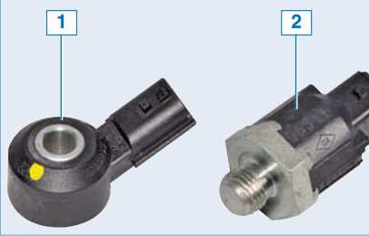
Placement of the clutch pedal status sensor 1, the brake signal toggle switch 2 and the gas pedal module 3 in the passenger compartment (for clarity, it is shown with the instrument panel and steering column dismantled)
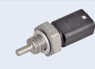
Renault Duster clutch pedal status sensor
Along with the above sensors, in order to maintain optimal engine operating conditions under various operating conditions, the ECU also uses signals from the clutch pedal status sensor (car with a manual transmission) or automatic transmission sensors, brake signal toggle switch, wheel speed sensors (ABS). Based on the signals from the clutch pedal status sensor and the brake signal toggle switch, the ECU distinguishes between depressed and not depressed states of the pedals. When the clutch pedal is depressed, the ECU limits the supply of fuel to the cylinders. The ignition system is part of the engine management system and consists of individual ignition coils and spark plugs for each cylinder. There are no high-voltage cables in the ignition system - the tip of the ignition coil is put directly on the spark plug.
Brake signal
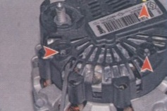
switch Renault Duster ignition coil The
control of the current in the primary windings of the ignition coils is carried out by the computer (depending on the engine operation order). The ignition coil is non-separable, in case of failure it is replaced. Spark plugs EYQUEM RFC58LZ2E, SAGEM RFN58LZ, CHAMPION RC87YCL or equivalents from other manufacturers, with noise suppression resistor (resistance 6.0 ±1.5 kOhm). The gap between the electrodes of the candle is 0.9-1.0 mm. Turnkey hexagon volume - 16 mm.
Source: http://avtorial.ru/Renault/Renault_Duster-36.html