Tools:
- Key with Torx tip (asterisk) Т30
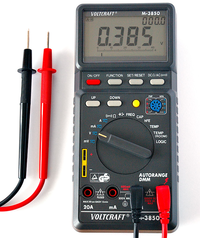
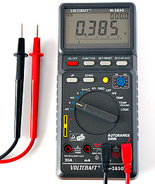
- High impedance digital tester
- Open-end wrench 17 mm
- Puller
- Small flat screwdriver
- Screwdriver flat medium
Parts and consumables:
- Scotch
- Airbag
- Spiral train
Notes:
I had an SRS malfunction (constant flashing of the airbag lamp and a monotonous female voice when starting the engine with a suggestion to visit the Nissan service). The verdict of the diagnostic scanner sounded like a “driver's airbag malfunction” and an attempt to erase the error code ended in failure.
To enter the diagnostic mode of the SRS system, you must:
1. Turn on the ignition and wait 7 seconds (until the airbag light goes out);
2. Within 1 second after the light goes out, turn off the ignition, wait more than 3 seconds and turn on the ignition again;
3. Repeat steps 1.2 THREE times, after that, after 7 seconds, the airbag lamp will start to issue an error code (in this diagnostic mode, the machine will remain permanently, even if the ignition is turned off). If at the time of diagnosis the malfunction is eliminated, this operation erases the error code of the SRS
4 system from the memory. To return from the diagnostic mode to the user mode, it is enough to turn off and immediately turn on the ignition for 1 second.
Fault codes (throws out long and short flashes of the lamp):
12 (one long, two short) - malfunction of the driver's airbag, including a spiral loop;
17 - malfunction of the airbag processor;
18 - malfunction of the passenger airbag;
16 - only for G35, malfunction of the front shock sensor (behind the grille, the Skyline does not have this sensor);
11 - malfunction of the right seat belt pretensioner;
13 - malfunction of the left seat belt pretensioner;
23 - malfunction of the right shock sensor;
24 - malfunction of the left shock sensor;
21 - malfunction of the right side cushion (side module in the back of the seat);
22 - malfunction of the left side cushion (side module in the back of the seat);
25 - malfunction of the right curtain-cushion;
26 - malfunction of the left curtain-cushion;
So, our code 12 is a driver airbag malfunction.
1. Having previously disconnected the battery and after waiting at least three minutes (as the manual says), we check all the yellow harnesses and connectors behind the steering column plastic protection.
2. We check the airbag module, for which, with an asterisk "T30" with a hole, after removing the nickels of the plugs, we unscrew the two bolts securing the steering airbag, carefully dismantle the module by disconnecting the connector.
3. We call the pillow with a tester.
Notes:
The manual strictly forbids doing this, so only a high-resistance digital tester should be used. To select the “correct” tester, it is necessary in the resistance measurement mode (Ohm), connect the LED to the tester’s probes and check its glow at different polarities (you can also check the language). If voltage is present on the probes, then this tester will not work.
4. Let's move on to a spiral loop, it's interesting, but when dialing, the loop itself showed serviceability (presumably, the breakage was inconsistent and depended on the position of the steering wheel).
5. We unscrew the central nut by 17, and with a puller (a locksmith made one for me at work in 30 minutes), we pull the steering wheel off the slots. There are marks on the steering wheel hub and axle, we put them on them during reassembly.
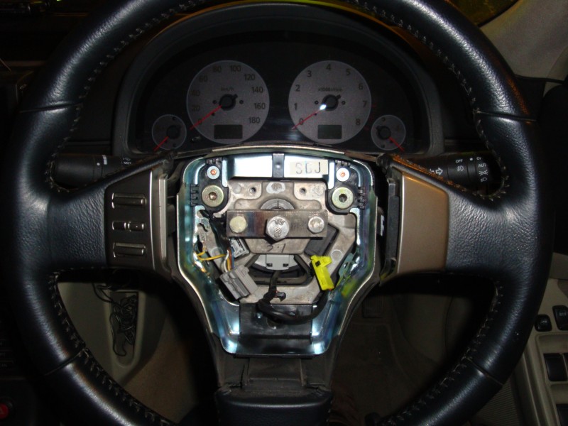
6. Remove the plastic protection from the steering column.
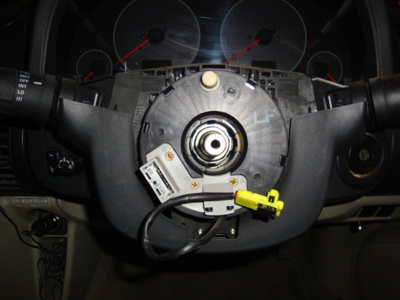
7. The connectors to the spiral cable from the engine side are removed and installed cleverly, in addition to the latches, they still need to be shifted one relative to the other, otherwise they cannot be put back.
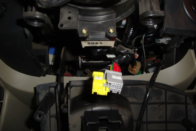
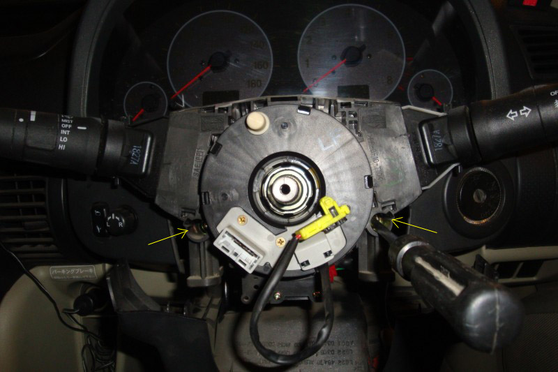
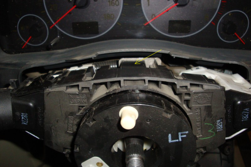
8. The cable housing with steering column switches is attached to the column with two screws and one latch:
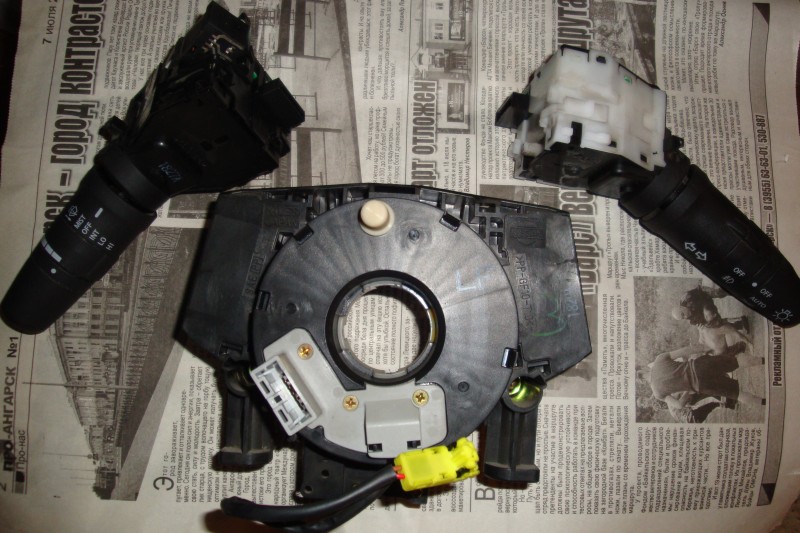
9. Next, snap off the side switches from the cable body.
10. We start disassembling the cable body from the central sleeve, it is on 4 latches, you need to squeeze them out at the same time. We memorize, write down, mark the details for reassembly. In order not to inadvertently twist the internal conductors of the cable during disassembly (the cable itself is designed only for a full four turns), we temporarily fix the connectors with adhesive tape, unscrew the existing screws, and disconnect the remaining parts.
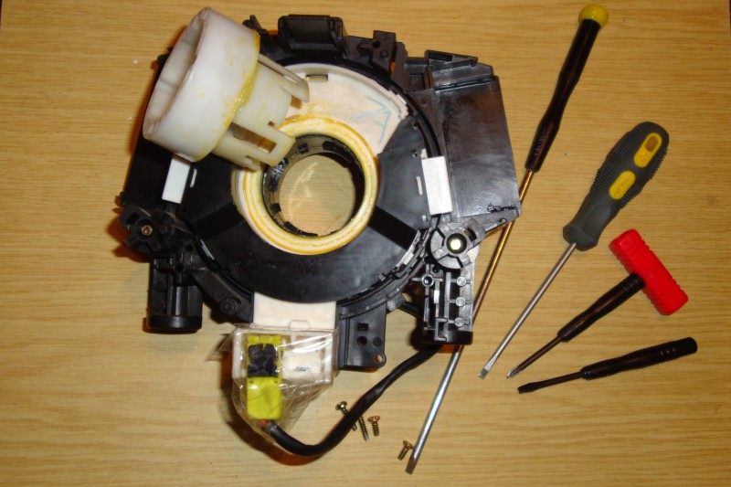
11. Well, we got there, the cable itself is a single structure with molded connectors at the ends.
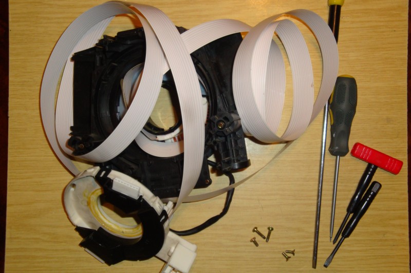
12. On the inner (the one closer to the axis) end, a plastic auxiliary tab is glued, which prevents the cable from sharply bending near the connector.
Notes:
When reassembling, it is important to put the petal with the cable behind a special ledge on the inner clip, otherwise there will be no rigid fixation, and the cable will bend in this place. I can’t say for all 100, because I didn’t immediately pay attention, but it seems to me that my cable was not inserted correctly for this protrusion during manufacture. In addition, for some reason, the petal is not made solid and the outermost conductors (they are airbags) are unreliably protected from kinks. The estimated location of the break is indicated by an arrow. As a repair option, a dubious place can be cleaned and contact restored with a drop of solder.
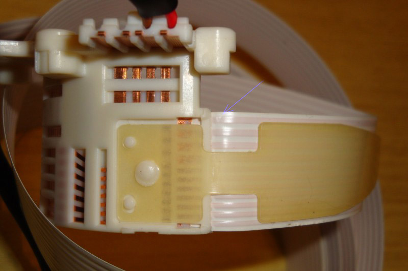
13. The photo below shows that next to the airbag wire, there are two unused contacts, these two backup conductors run along the entire loop and go to another connector. On the engine side, on the mating yellow connector, only two contacts are inserted into the block, and the other two are not used. I don’t know for what reason they ended up in the loop, perhaps they were left as a legacy for the Infiniti G35 twin-fuse airbag or were scheduled for cruise control, it doesn’t matter.
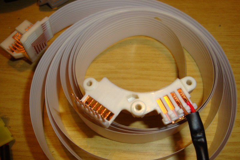
14. The fact is that this allows you to use backup conductors by connecting them in parallel with regular ones using jumpers at both ends of the loop. Cushion side terminal block:
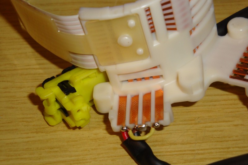
15. Terminal block from the engine side (the jumper was made in the form of a bracket):
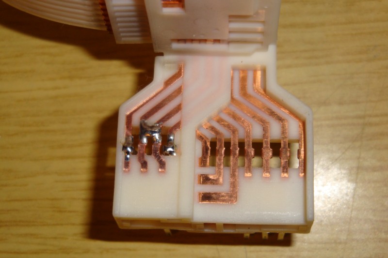
16. The same, reversed:
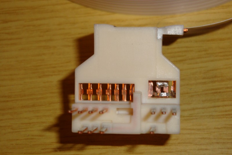
17. When re-mounting on the steering column, the rotating parts of the cable must first be oriented so that relative to the neutral position there is a rotation of two turns in one direction and the other. If this is not done, the cable will definitely break while driving. After erasing the error, everything became as before, I have been driving for almost a month.
Source: http://www.primera-club.ru/f/baza-znaniy-elektrika-p12/16063-neispravnost-srs-voditelya/
![P12 [2001 - 2008]](/uploads/Nissan_Primera_Primera_1.9_DCi_Sedan.jpg)
