![1 generation [2003 - 2007]](/uploads/Mitsubishi_Outlander_I_2003_-_2008_.jpg)
![3 generation [2012 - 2014]](/uploads/3.png)
![XL [2005 - 2012]](/uploads/4d137205da66f_.jpg)

Tools (for 4B12/4B11 engines):
- screw jack
- balloon wrench
- Screwdriver flat medium
- Ratchet wrench
- Extension (with cardan)
- Head 10 mm
- Head 12 mm
- Straight ring wrench 16 mm
- torque wrench
- Marker
- Hex wrench for fixing the tensioner (or pin)
- Tester
- Wheel chock (shoe)
- Knife (or scissors)
Tools (for 6B31 engine):
- 10 mm bent box wrench
Parts and consumables:
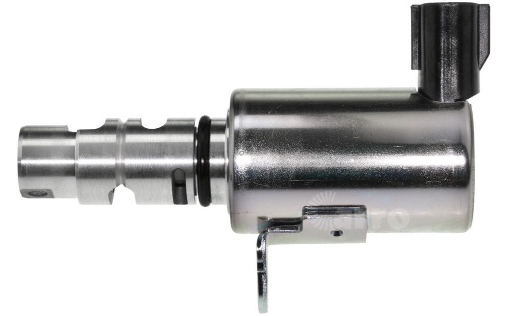
- Oil control solenoid valve MIVEC 1028A021 / 1028A109 intake camshaft (for 4B12 and 4B11 engines, if required)
- Oil control solenoid valve MIVEC 1028A022 / 1028A110 exhaust camshaft (for 4B12 and 4B11 engines, if required)
- MIVEC 1028A053 oil control solenoid valve for exhaust camshaft (for 6B31 engine, if required)
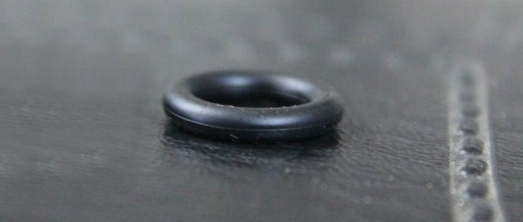
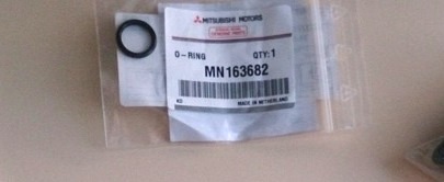
- Oil control valve O-ring MN163682 - 2 pcs. (for 4B12 and 4B11 engines)
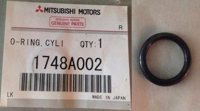
- O-ring gasket for oil control valve 1748A002 - 2 pcs. (for 6B31 engine)
- Motor oil
- wires
- Insulating tape
- Rope or wire (for 4B12/4B11 engines)
Notes:
The Mitsubushi MIVEC (Mitsubishi Innovative Valve timing Electronic Control) system of the 4B12 and 4B11 engines allows you to smoothly change the valve timing in accordance with engine operating conditions. This is achieved by rotating the intake camshaft relative to the exhaust shaft in the range of 25° (crank angle) for the 4B11 engine or 40° (crank angle) for the 4V12 engine and rotating the exhaust camshaft relative to the intake shaft in the range 20 ° (according to the angle of rotation of the crankshaft).
As a result, the moment when the intake valves begin to open and the exhaust valves close changes, and, consequently, the value of the “overlapping” time (that is, the time when the exhaust valve is not yet closed, and the intake valve is already open) changes up to its exclusion (zero value).
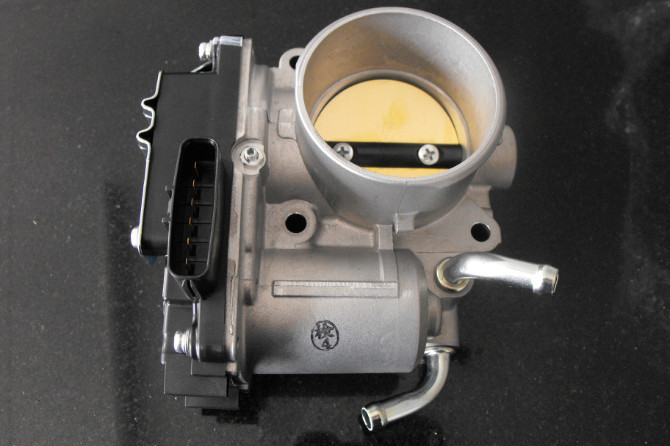
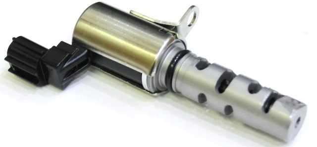
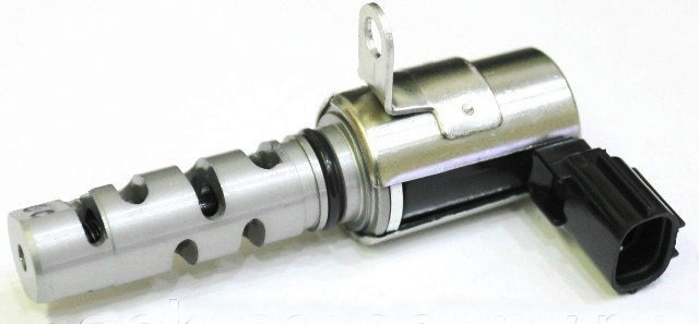
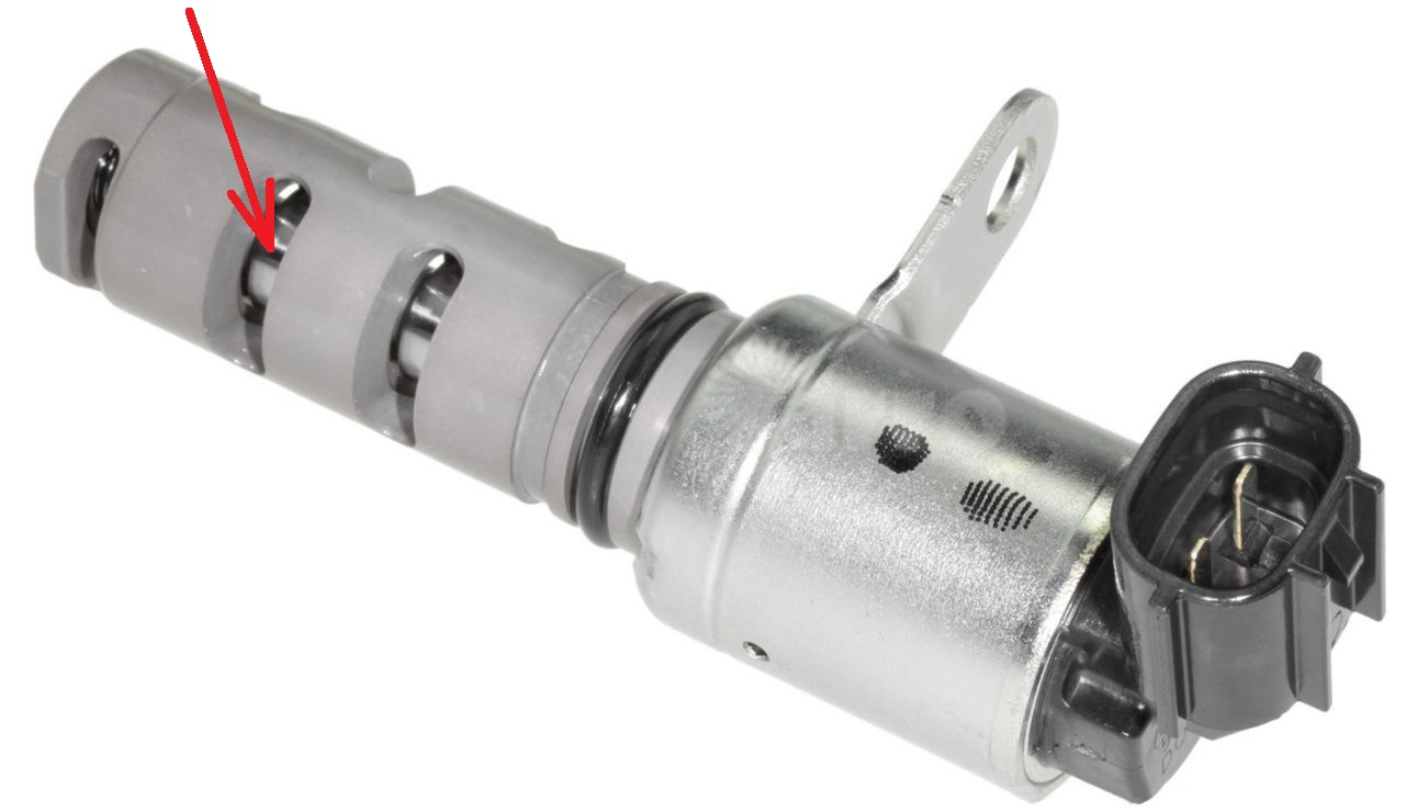
The Mitsubishi MIVEC system is controlled by an oil control solenoid valve (OCV - Oil Control Valve).
At the signal of the engine control unit, the electromagnet moves the main spool through the plunger, bypassing the oil coming from the engine lubrication system line in one direction or another.
In the event of a malfunction, the system control will be disabled and the camshaft angle will be set to correspond to the latest start of the intake valves opening (maximum lag angle) and the earliest start of exhaust valve closing (minimum lag angle).
The Mitsubushi MIVEC (Mitsubishi Innovative Valve timing Electronic Control) system of the 6B31 engine regulates the opening of the intake valves depending on the number of revolutions of the crankshaft. This system allows you to set the optimal amount of valve opening for each moment of engine operation, which allows you to achieve increased power, better fuel efficiency and less toxicity of exhaust gases.
The main elements of the MIVEC system are a camshaft with three cams per pair of valves and rocker arms with rollers running around each camshaft cam. At low engine speeds, each low cam rocker runs around its cam profile. At the same time, the opening of the intake valves is minimal. At high speed, the solenoid valve supplies oil to the channel of the intake rocker shaft. Plungers move under pressure inside the rocker bushings. Each plunger fits into the gap between the high cam rocker toe and the low cam rocker. The kinematic chain is closed, and both rocker arms begin to work along the profile of the high cam. As a result, the valve stroke increases, the filling of the cylinders improves and the engine develops more power.
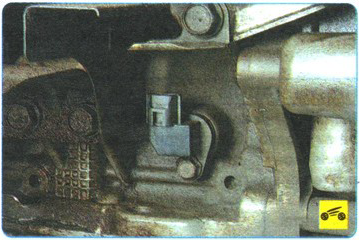
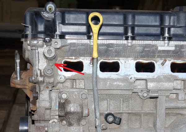
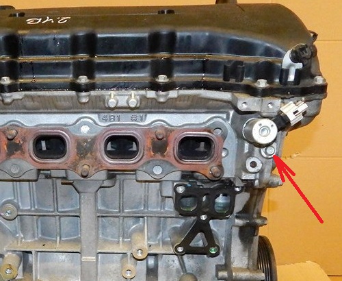
The controls for the MIVEC intake valve adjustment system are located at the rear of the cylinder head.
In the event of a malfunction of the MIVEC system, its control stops and the gas distribution mechanism operates according to the usual classical scheme.
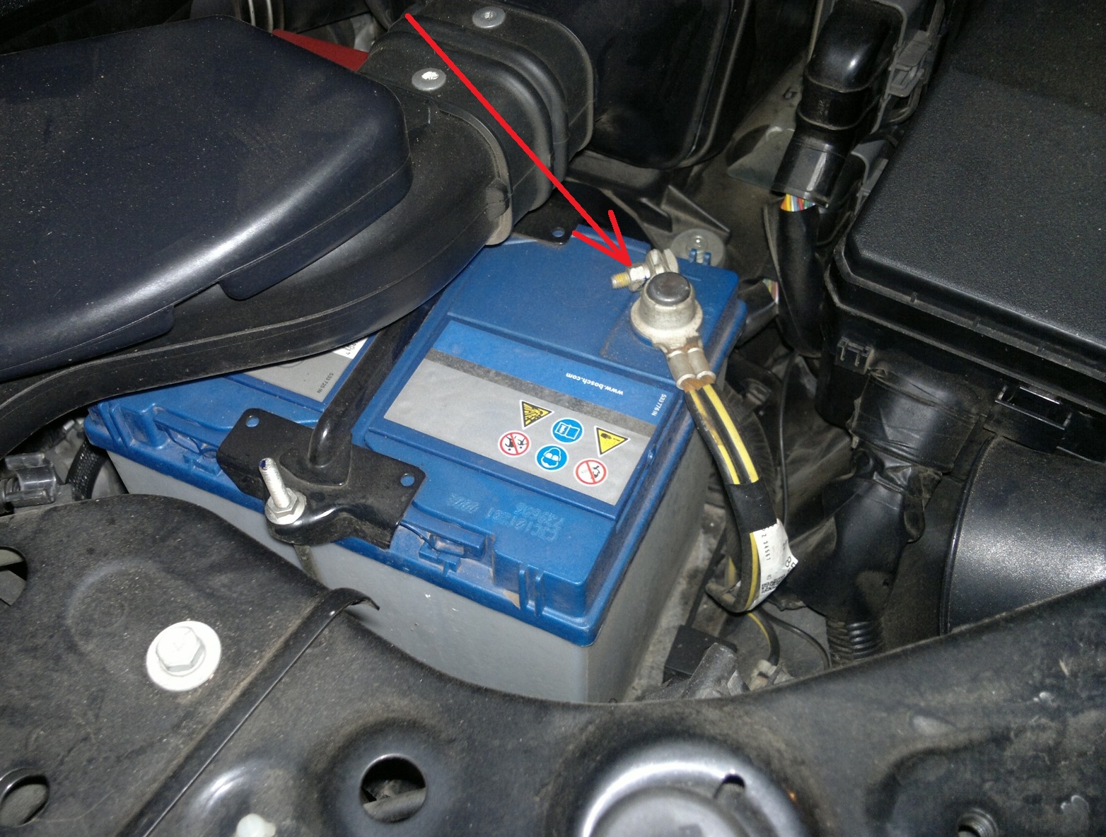
1. Disconnect a wire from the plug minus the storage battery.
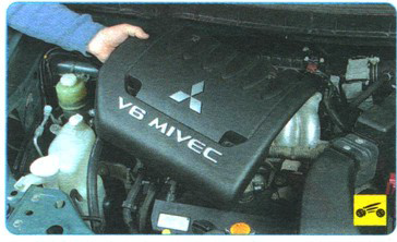
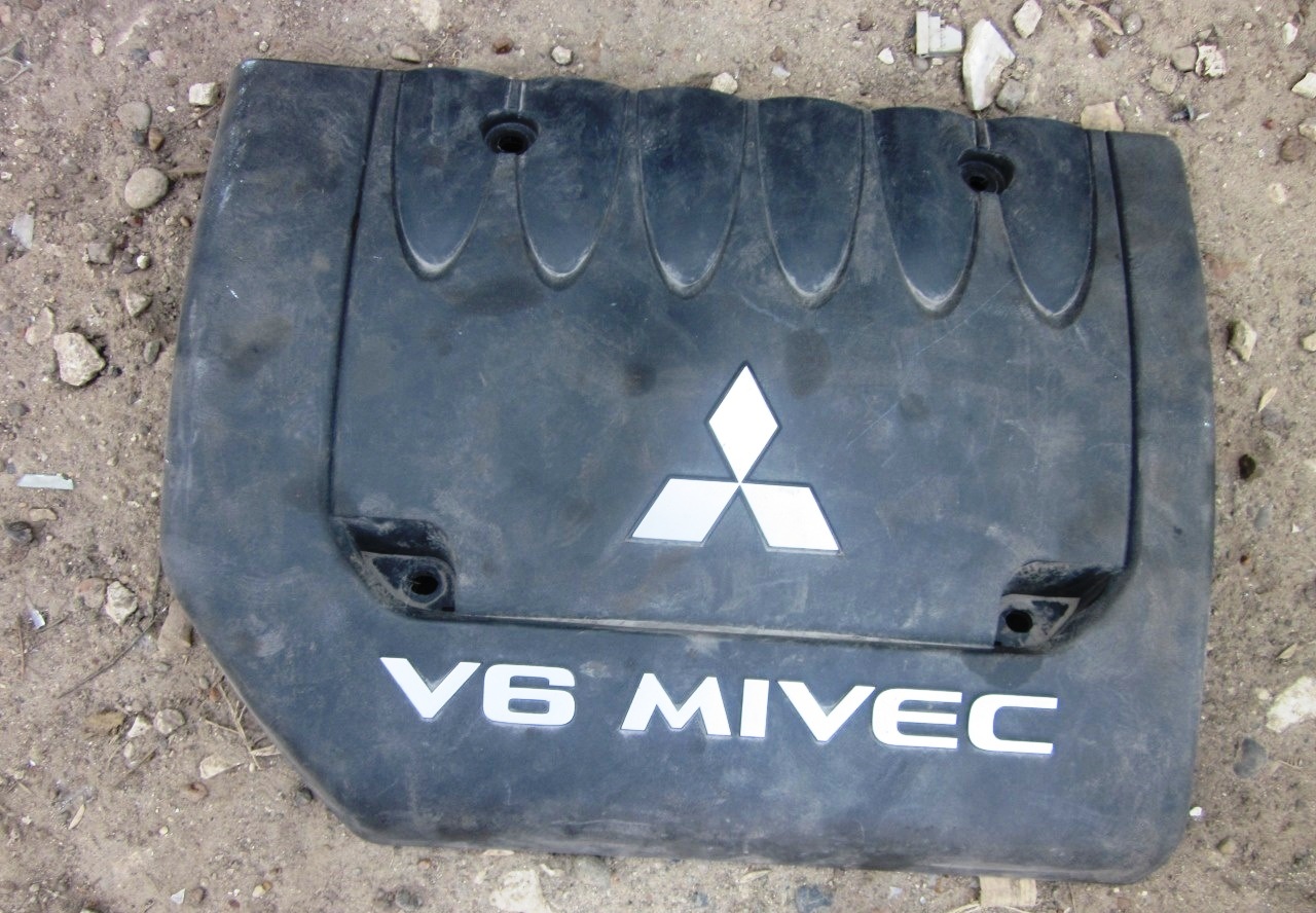
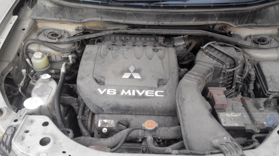
2. Remove the decorative engine cover as described here .
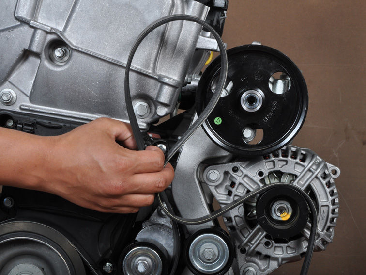
3. (4B12/4B11 engines) Remove the engine accessory drive belt as described here .
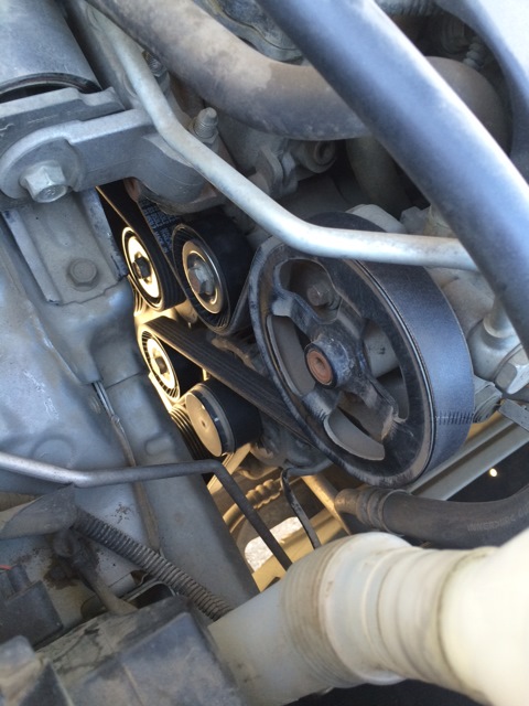
4. (4B12/4B11 engines) Remove the power steering pump assembly from its bracket with the hoses attached (shown with engine removed for clarity).
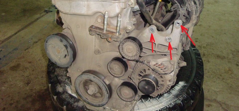
Note:
After removal, use a wire or rope to hang the power steering pump assembly with hoses on the body in a place where they will not interfere with the removal and installation of other parts.
It may be possible to remove the intake valve MIVEC valve bolt without removing the accessory drive belt and power steering pump.
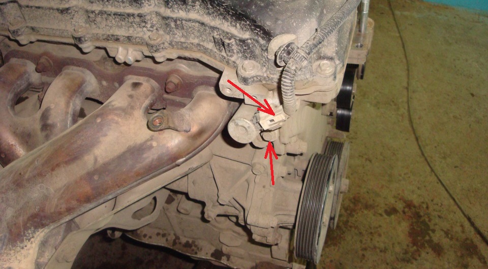
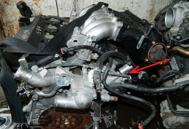
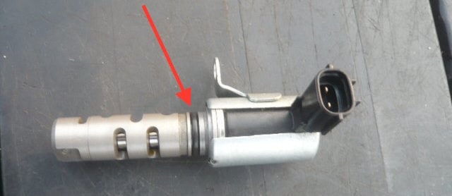
5.1. (engines 4B12/4B11) Squeezing the clamps of the wire block, disconnect it from the connector of the oil control solenoid valve on the side of the exhaust valves and unscrew its fastening bolt using a 10 mm socket (see the first photo below). Do the same with the inlet valve (see second photo below).
5.2. (engine 6B31) Squeezing the clamps of the wiring harness, disconnect it from the connector of the oil control solenoid valve and unscrew the bolt securing it to the cylinder head using a 10 mm head.
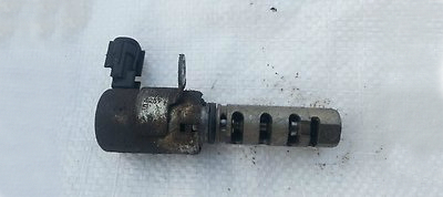
6. Remove valve(s) with O-ring from cylinder head.
8. To test the MIVEC valve, connect a tester in ohmmeter mode to the valve leads. Valve resistance at 20°C should be 6.75 - 8.25 ohms.
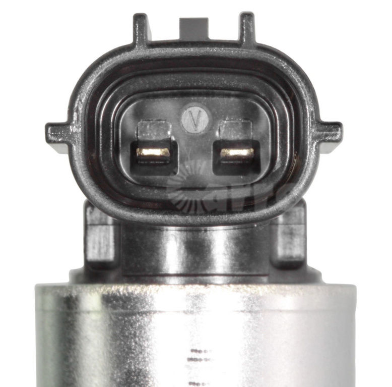
9. Apply battery voltage to the valve leads and check that the valve spool moves.
10. Apply a small amount of engine oil to the O-ring and install it to the oil control valve.
Note:
Use only new O-rings for valves.
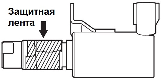
To prevent damage to the ring gasket, wrap protective tape around the working part of the solenoid valve, on which the oil passages are located, before installation.
11. Install the solenoid(s) valve(s) to the cylinder head.
12. Tighten the valve(s) mounting bolts to a nominal torque of 11 ± 1 Nm.
13. Install all removed parts on the Outlander HL engine in the reverse order of removal.
The article is missing:
- Tool photo
- Photo of parts and consumables
Source: carpedia.club