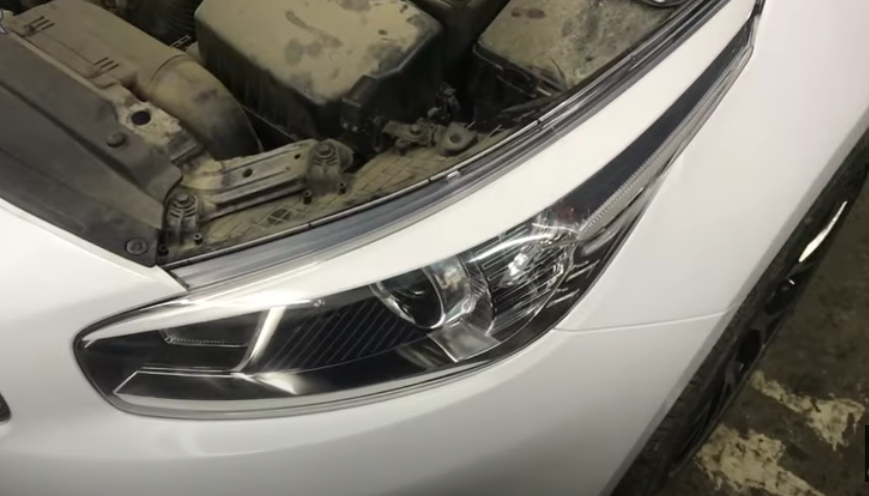
![2 generation [2012 - 2015]](/uploads/Kia_Ceed_2015_-_2016.jpg)

Tools:
- Ratchet wrench
- Head 10 mm
- soldering iron
- Electric drill (if needed)
- Drill bit 10 mm (if necessary)
- Phillips screwdriver, medium
- Small flat screwdriver
- magnifying glass
- Hair dryer for soldering chips
- Tweezers
Parts and consumables:
- Tsaponlak
- Front headlight (if required) (92101-A2000 headlight left, 92102-A2000 headlight right)
- Printed circuit board - substrate for the board (for self-manufacturing)
- A set of elements for the board (for self-manufacturing)
Note:
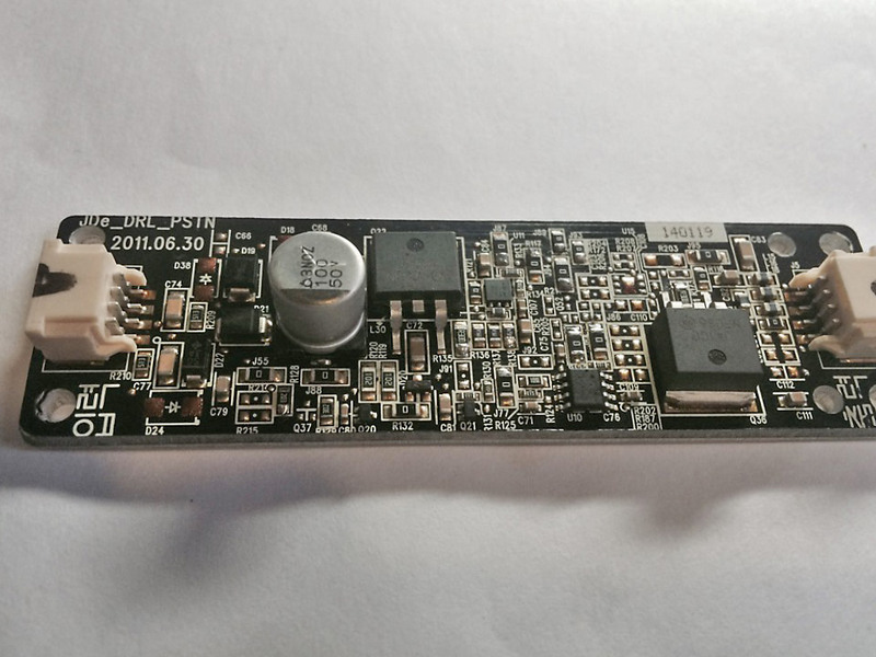
Many are faced with the problem of a non-working Kia Sid DRL. Eyelashes on Kia Sid may not work correctly and not in all modes. The whole problem is in the controllers (boards) that are responsible for the DRL inside the headlights. For native boards, the temperature regime does not have a margin relative to the operating temperatures in the headlight. Due to the aluminum substrate of the board and overheating, the contact bursts and / or soldering disappears. In this article, you will learn how to repair a Kia Sid DRL by repairing an existing standard DOX lamp control board or by making your own. An alternative solution to this problem can only be to replace the headlight completely.
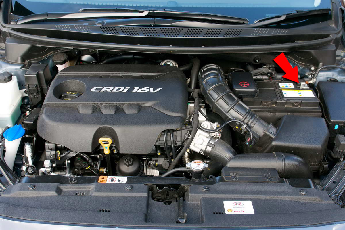
1. Disconnect the negative terminal from the battery.
2. Remove the headlights.
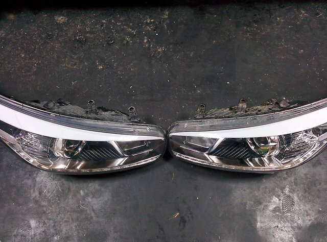
3. Remove the bulbs from the headlight.
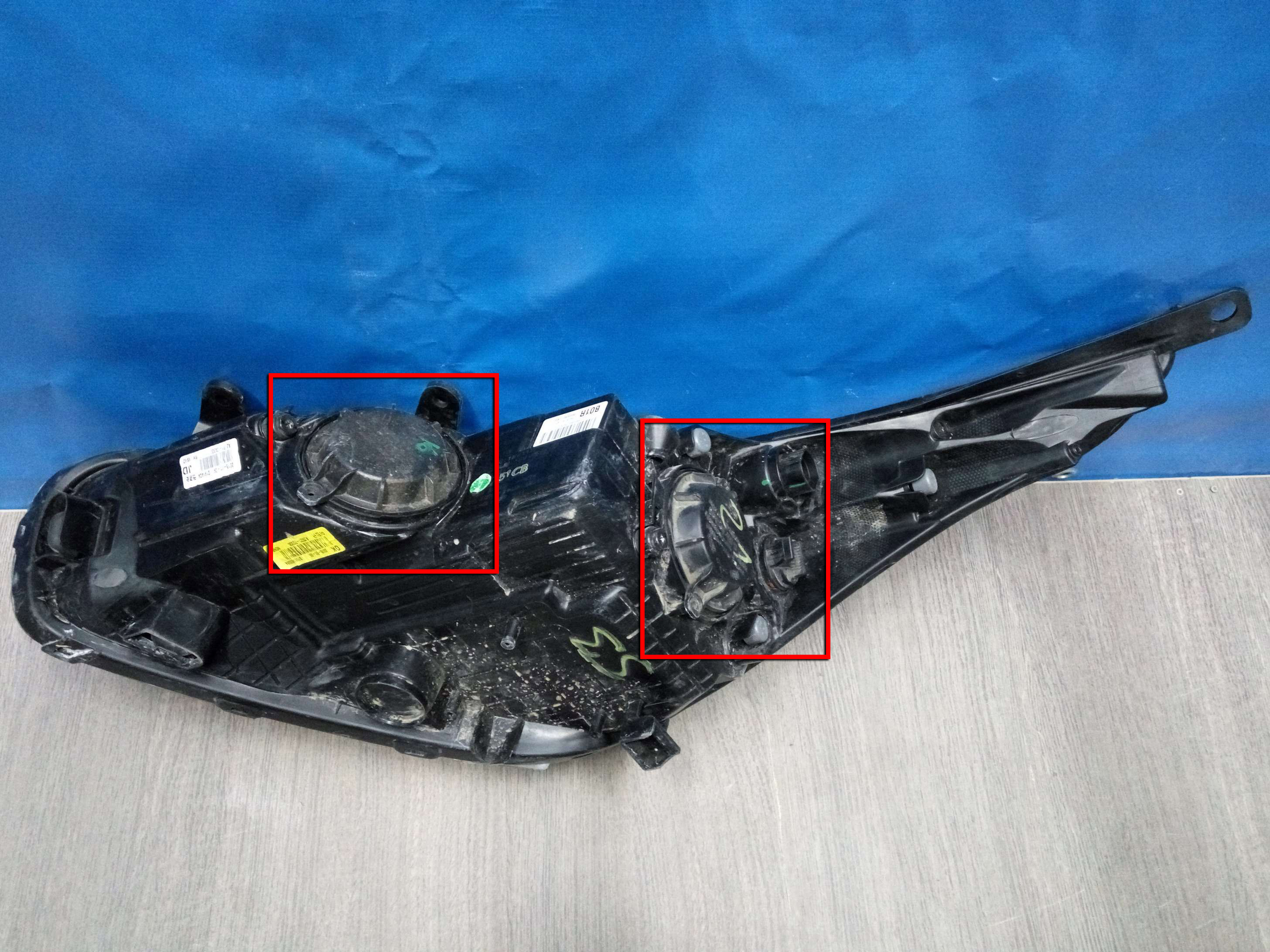
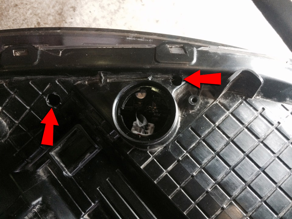
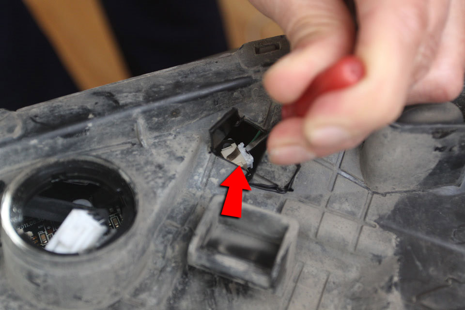
4. Using a soldering iron (or drill), make two holes in the spotlight above the board screws.
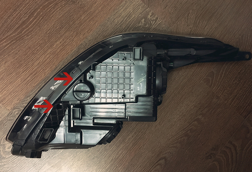
Hole locations.
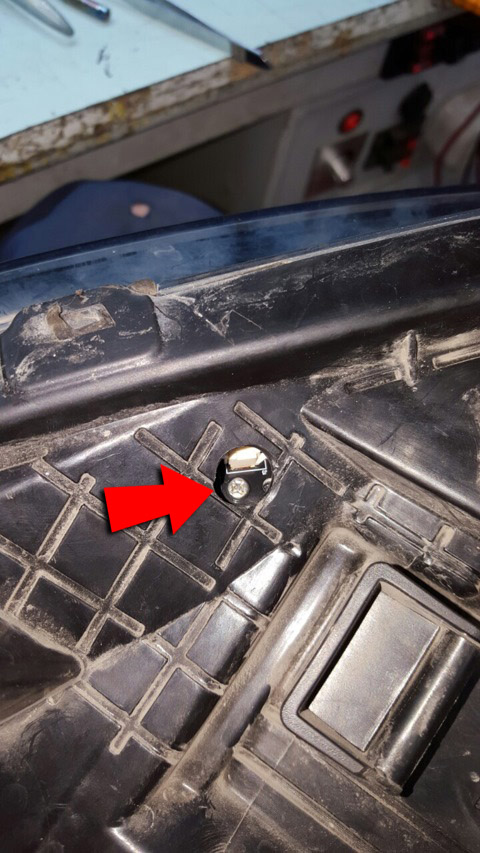
3. Unscrew the board fixing (fixing the board with two screws).
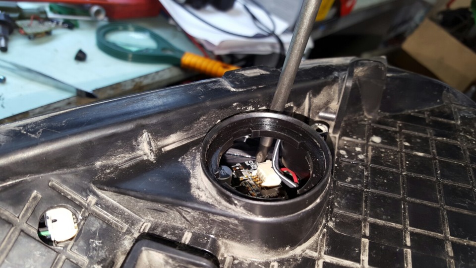
4. Using a flat screwdriver, press the tab on the DRL wire block and unfasten the block from the board.
5. Remove the board through the low beam lamp hole.
Note:
Examine the board through a magnifying glass for solder cracks. Before working on soldering the board, you need to warm it up well (a 4 mm thick aluminum board). Take a hair dryer for soldering chips, warm up and immediately solder.
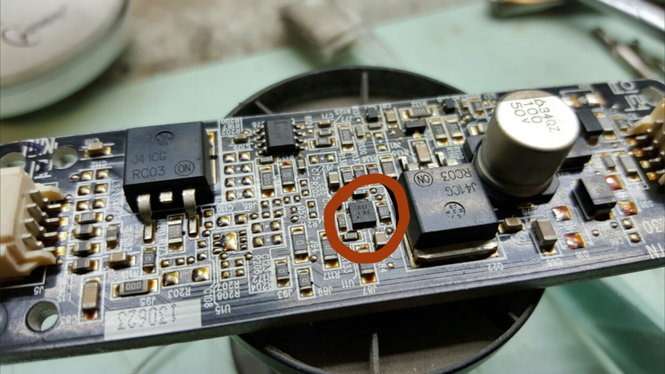
6. The circled area has a micro crack in the solder. Warm up and solder.
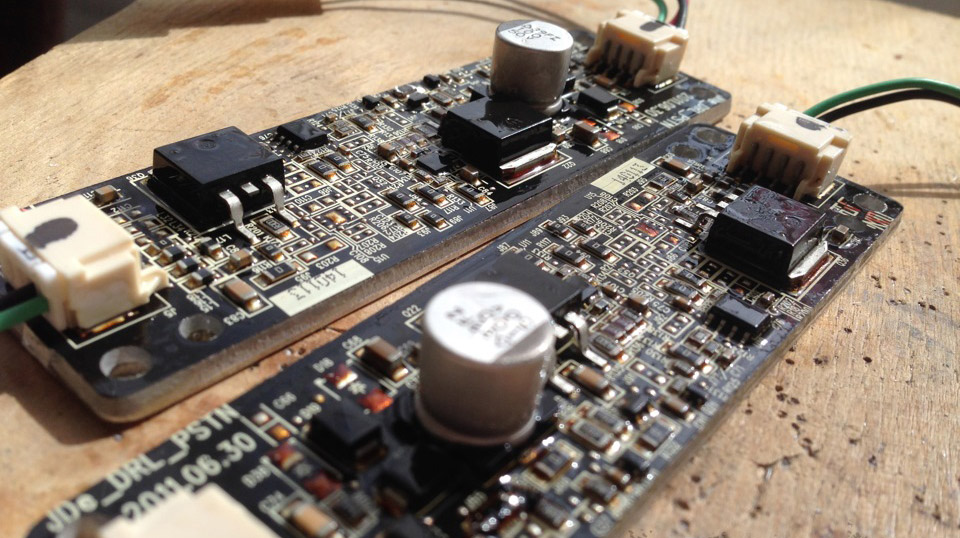
7. On the other board, the "jumper tooth" in the form of zero resistance fell off (the solder cracked and it fell off). The procedure is similar to item 6.
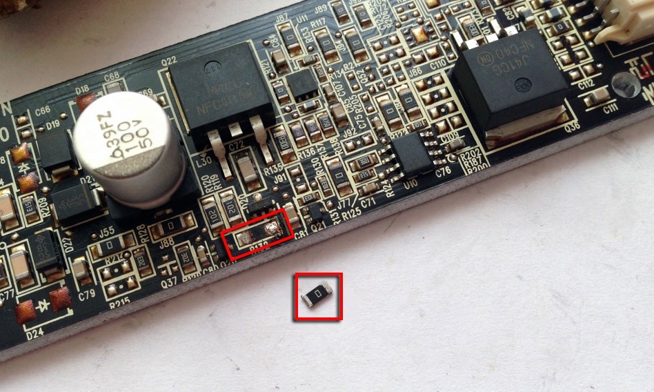
soldered resistor
Note:
If the board is in a very bad condition, and resoldering the same board does not seem like a reliable long-term solution, then you can do something more radical and replace the board by completely making it yourself. An example of a homemade board and the necessary circuits are given at the bottom of the article.
8. Cover the repaired boards with zaponlak for greater protection of circuits and elements.
9. Install and screw the board in the reverse order of removal.
Note:
Straighten the power tail of the board and push the board back behind it.
10. Solder the holes on the headlight housing.
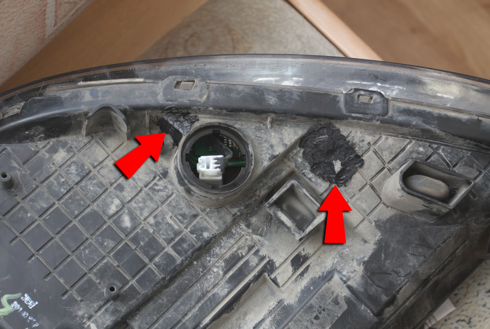
Soldered holes on the headlight housing.
11. Establish headlights in an order, the return to removal.
Making a board DRL Kia Sid
The board is made without connectors. They will need to be soldered from the original boards and transferred to new boards.
To do this, it is recommended to use a soldering dryer at 320-350 degrees, preheating the board from below. Then quickly transfer the hair dryer to the top side of the board on the connector and remove it with tweezers. So the plastic doesn't get damaged.
Warning:
Payment cannot be made by hand. It is necessary to use tweezers, "Third hand", or something similar.
Note:
If you only have a soldering iron, you can try using a heated iron as an option to heat the board. Put the board on it and carefully remove it with the same tweezers.
In addition to the soldering of the board itself, its firmware is also needed, the archive with which is located here .
Recommended board version: ATTiny13.
Recommended firmware: tiny13_without_soft-start_with_pause.hex
Differences between the original board driver and the manufactured one:
- A slight pause between switching operating modes (DRL bright, DRL normal) is about 0.1 seconds.
- No flickering eyelashes.
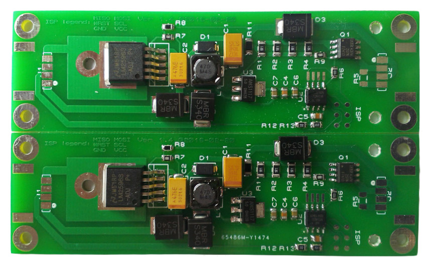
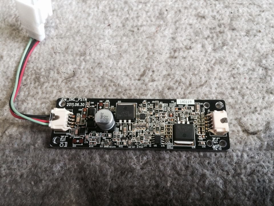
Front view of self-made DRL board
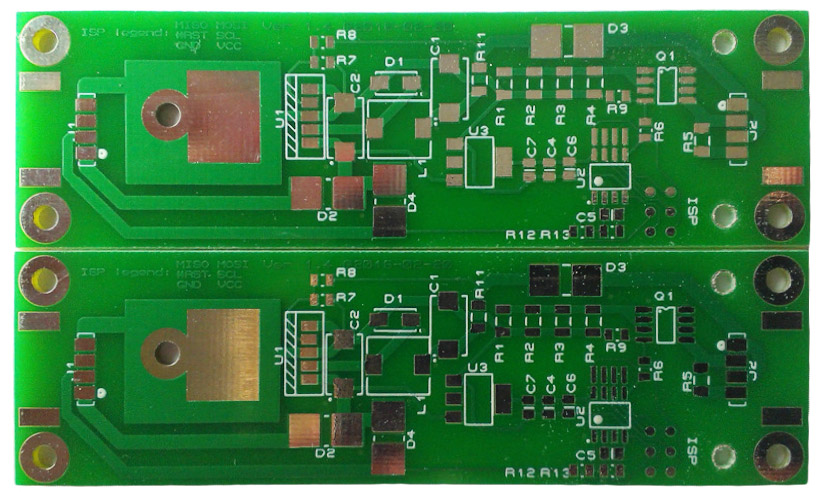
Rear view of self-made DRL board
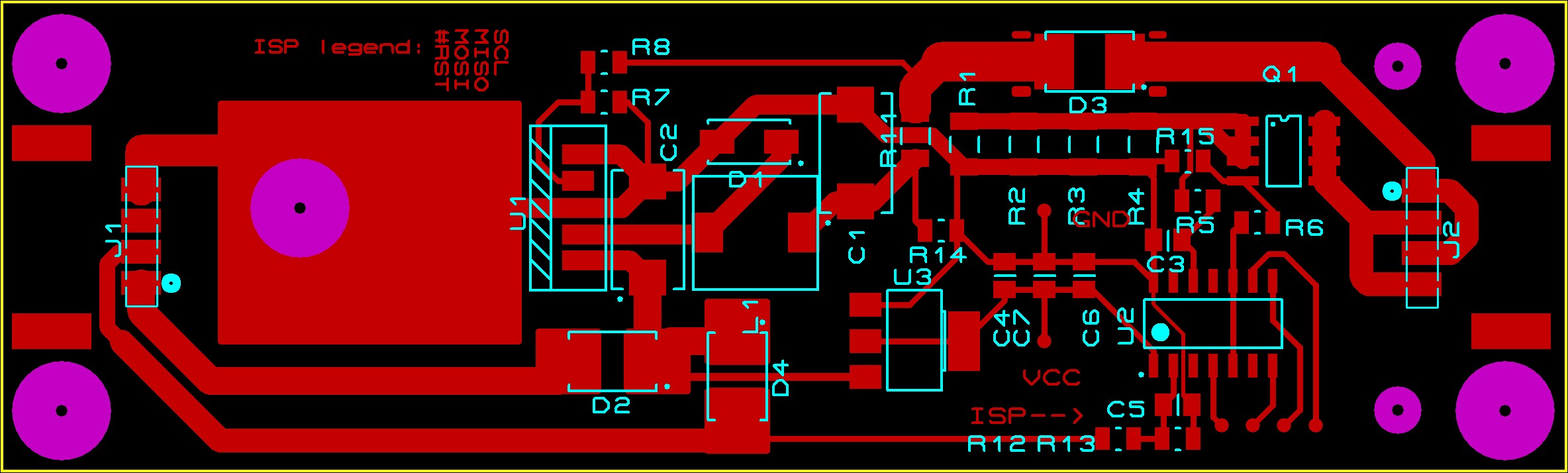
PCB diagram for the manufacture of DRL board
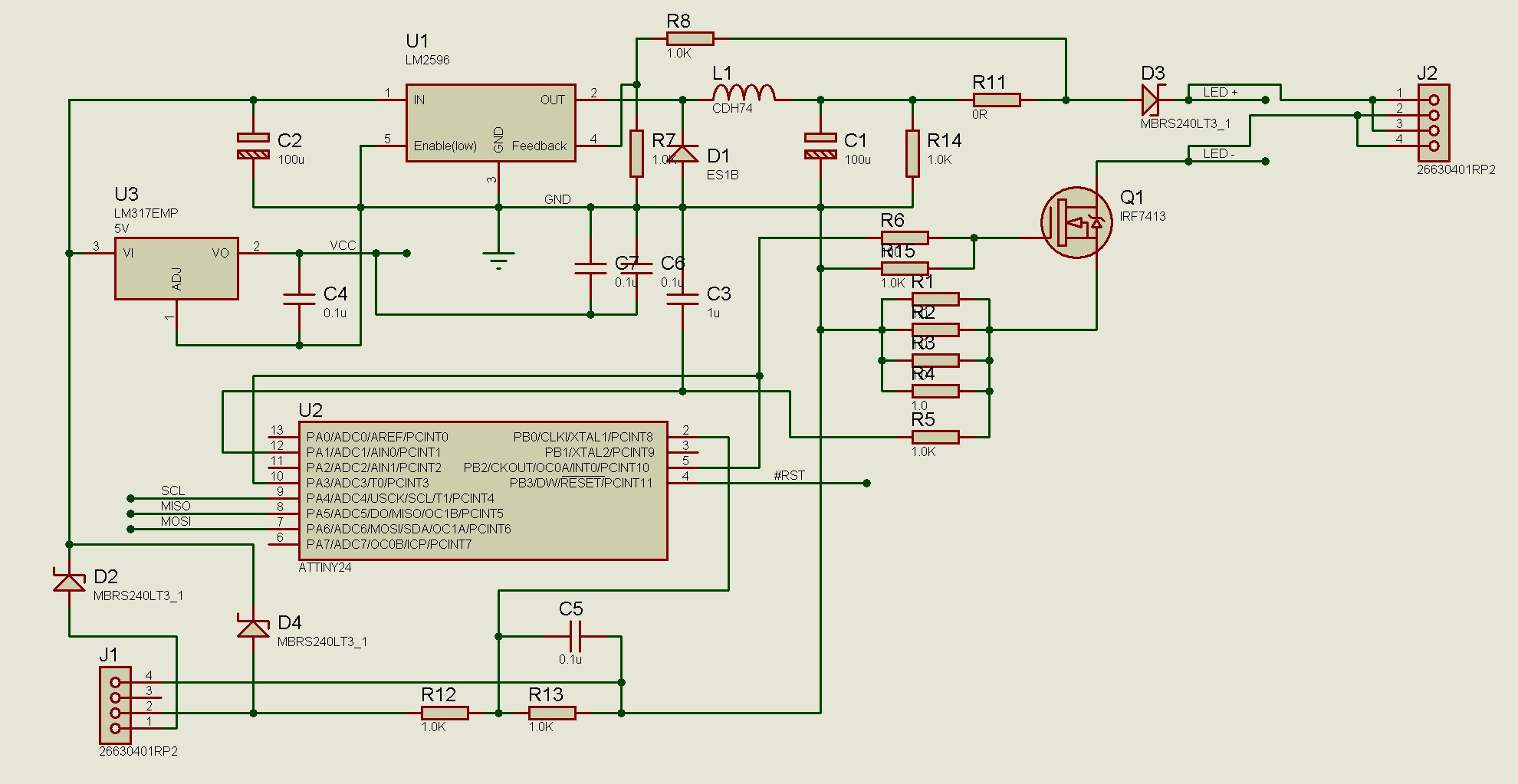
Scheme of elements of the DRL board
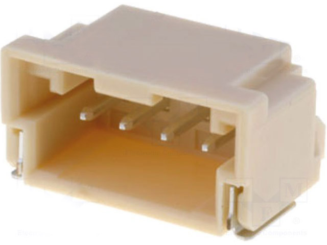
Connector on MOLEX board 502352-0400
The article is missing:
- Tool photo
- Photo of parts and consumables
Source: http://carpedia.club/