![1 generation [2003 - 2007]](/uploads/Mitsubishi_Outlander_I_2003_-_2008_.jpg)
![3 generation [2012 - 2014]](/uploads/3.png)
![XL [2005 - 2012]](/uploads/4d137205da66f_.jpg)

Note:
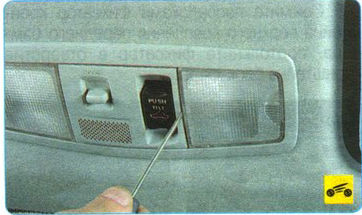
Below is an electrical diagram of the Mitsubishi Outlander HL 6B31 engine cooling system to understand the functionality of the individual elements of the system and their relationship.
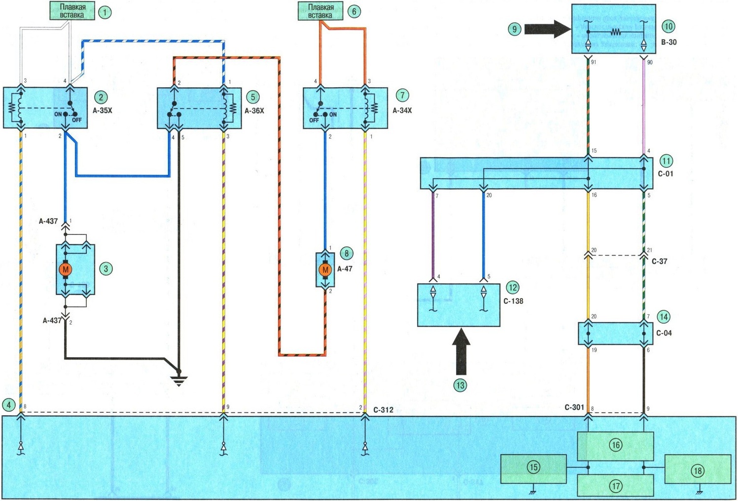
1. Scheme of the engine cooling system 6B31 Mitsubishi Outlander HL:
1 - fuse;
2 - air conditioner fan relay;
3 - electric motor of the fan of the conditioner;
4 - electronic control unit ETACS;
5 – fan control relay;
6 - fuse;
7 – radiator fan relay;
8 - radiator fan motor;
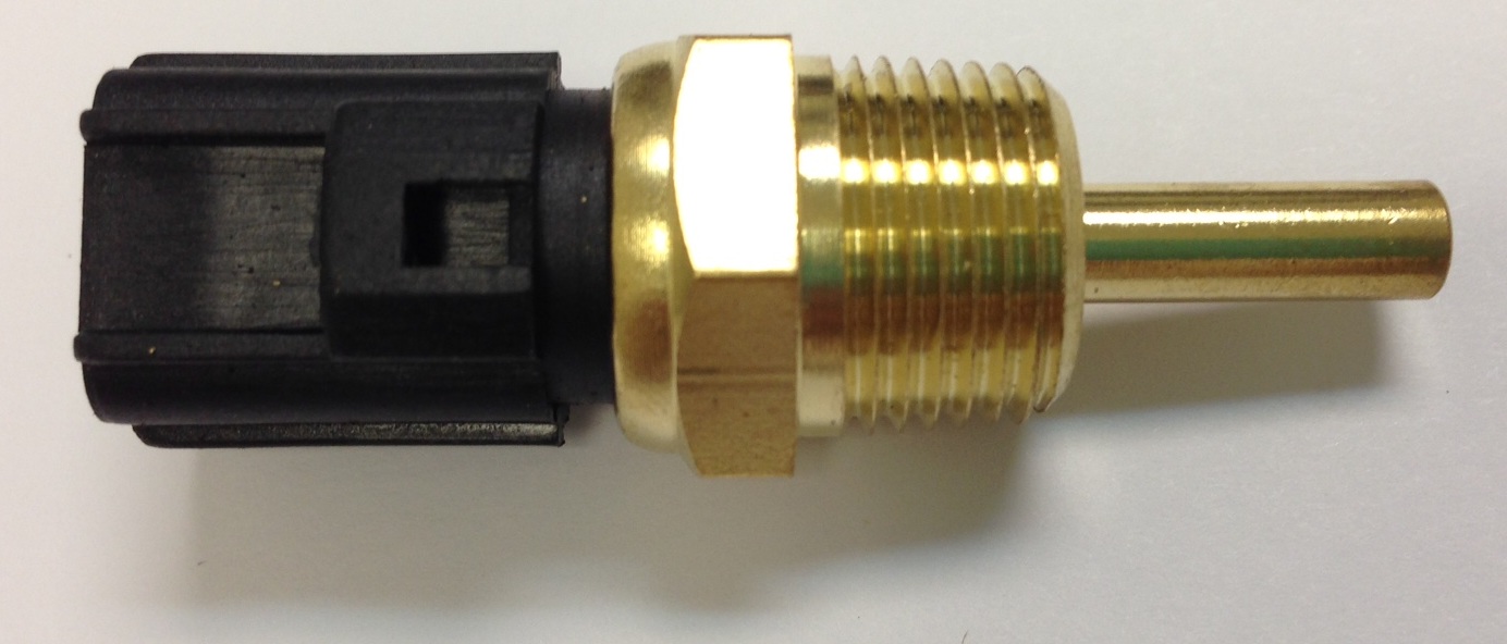
9 - input signal (coolant temperature sensor);
10 - electronic engine control unit;
11 – CAN 3 connector;
12 - electronic control unit for automatic transmission;
13 - input signal (output shaft speed sensor);
14 – CAN 2 connector;
15, 18 – analog interface circuit;
16 - conjugation circuit;
17 - starting circuit.
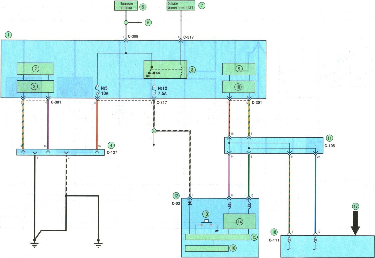
2. Scheme of the engine cooling system 6B31 Mitsubishi Outlander HL:
1 - electronic control unit ETACS;
2, 9 - starting circuit;
3, 10 - conjugation circuit;
4 - diagnostic socket;
5 - fuse;
6 - to the distribution system;
7 - ignition switch;
8 - ignition lock relay;
11 – CAN 1 connector;
12 – a combination of devices;
13 - rheostat;
14 – transmission line circuit;
15 – processor module;
16 - liquid crystal display;
17 - air conditioner switch;
18 - control unit for the air conditioning and ventilation system.
Source : Operation, maintenance and repair manual for Mitsubishi Outlender XL, Peugeot 4007, Citroen C-Crosser