![B10 [2006 - 2013]](/uploads/Nissan_Almera_Classic_2006-2013_.jpg)

The engine installed on Nissan Almera Classic cars is equipped with an electronic engine management system with distributed fuel injection. This system ensures that current emission and fumes regulations are met while maintaining high driving performance and low fuel consumption.
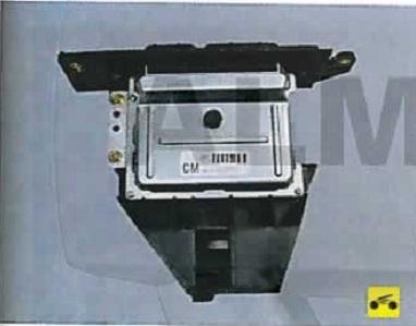
The control device in the system was an electronic control unit (ECU). Based on the information received from the sensor, the ECU calculates the parameters for fuel injection control and ignition timing control. In addition, in accordance with the embedded algorithm, the ECU controls the operation of the electric motor of the fan of the engine cooling system and the electromagnetic clutch for turning on the air conditioning compressor, performs the function of self-diagnostics of the system elements and notifies the driver of any malfunctions.
In the event of failure of individual sensors of the actuators, the ECU includes emergency modes that ensure engine performance.
The amount of fuel supplied by the injectors is determined by the duration of the electrical signal from the ECU. Electronic monitors data on the state of the engine, calculates the need for fuel, determines the required duration of fuel supply by injectors (signal duration). To increase the amount of fuel supplied, the duration of the signal increases, and to reduce the fuel supply - ) decreases.
The engine management system, along with the electronic control unit, includes sensors, actuators, connectors and fuses.
The electronic control unit (ECU) is connected by electrical wires to all sensors of the system. Receiving information from them, the rock performs calculations in accordance with the parameters and the control algorithm stored in the memory of the programmable read-only memory (PROM), controls the executive devices of the system. The program variant recorded in the PROM memory is indicated by the number assigned to this ECU modification.
The control unit detects a malfunction. identifies and remembers its code, even if the failure is unstable and disappears (for example, due to poor contact).
The unit supplies 12 V direct current to various sensors and switches of the control system. Since the electrical resistance of the power circuits is high, the test lamp connected to the system outputs does not light up. To determine the supply voltage at the computer terminals, a voltmeter with an internal resistance of at least 10 MΩ should be used.
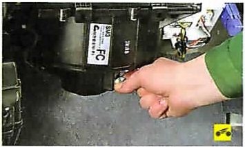
The ECU is not repairable and should be replaced if it fails.

The diagnostic connector is used to display fault codes from the ECU memory detected during the operation of the engine management system.
It is located in the passenger compartment in the driver's footwell under the instrument panel.
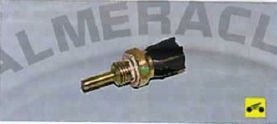
The coolant temperature sensor is installed in the engine cooling system. The sensing element of the sensor is a thermistor, the electrical resistance of which varies inversely with temperature. At a low temperature of the coolant (-40 * C), the resistance of the thermistor is about 100 kOhm, when the temperature rises to +130 ° C, it decreases to 70 Ohm.
The electronic unit feeds the temperature sensor circuit with a constant reference voltage. The sensor signal voltage is maximum on a cold engine and decreases as it warms up. Based on the voltage value, the electronic unit determines the engine temperature and takes it into account when calculating the injection and ignition control parameters. If the sensor fails or there are violations in its connection circuit, the ECU sets the fault code and remembers it. To eliminate the problem, check the reliability of the contact connections in the wiring to the sensor or replace the sensor.

The mass air flow sensor is located between the air filter and the throttle valve air inlet sleeve. The sensor signal is a DC voltage, the value of which depends on the amount of air passing through the sensor.
An air temperature sensor is built into the mass air flow sensor, the sensing element of which is a thermistor installed in the air stream.
The ECU supplies the sensor circuit with a constant reference voltage. The signal voltage of the sensor is maximum when the air in the intake pipe is cold and decreases as its temperature rises. From the voltage value, the ECU determines the intake air temperature and makes adjustments when calculating the ignition timing. If the sensor fails or there are violations in its connection circuit, the ECU sets the fault code and remembers it. If the ECU continues to generate a DTC with good contact connections in the wiring, replace the air temperature sensor.
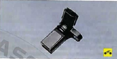
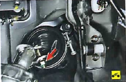
The inductive type crankshaft position sensor is designed to synchronize the operation of the electronic control unit with the TDC of the pistons of the 1st and 4th cylinders and the angular position of the crankshaft.
The sensor is installed at the rear of the engine opposite the setting disk located on the crankshaft. The driving disk is a gear wheel with equidistant cavities. Two teeth are cut off to create a synchronization pulse ("reference" pulse), which is necessary to coordinate the operation of the control unit with the TDC of the pistons in the 1st and 4th cylinders.
As the crankshaft rotates, the teeth change the sensor's magnetic field, inducing AC voltage pulses. The control unit determines the crankshaft speed from the sensor signals and sends pulses to the injectors.
If the sensor fails, the engine cannot be started.

The throttle position sensor is a potentiometer, one end of which is supplied with a "plus" supply voltage (5 V), and the other end is connected to ground.
From the third output of the potentiometer (from the slider) there is an output signal to the electronic control unit.
When the throttle valve is turned (from the impact on the control pedal), the voltage at the output of the sensor changes. When the throttle is closed, it is lower than 0.5 V. When the throttle opens, the voltage at the sensor output rises, when the throttle is fully open, it should be more than 4 V.
By monitoring the output voltage of the sensor, the controller corrects the fuel supply depending on the throttle opening angle (t .e at the request of the driver).
The throttle position sensor does not require adjustment, since the control unit perceives idling (i.e. full throttle closing) as a zero mark.
The camshaft position sensor (phase sensor) determines the TDC of the compression stroke of the piston of the 1st cylinder. The sensor signal is used by the controller to organize phased fuel injection in accordance with the order of operation of the cylinders. If a circuit malfunction occurs, the controller stores its code in its memory and turns on the signal lamp.

The oxygen concentration sensor (lambda probe) is screwed into the threaded hole in the exhaust manifold. A galvanic cell is located in the metal bulb of the sensor, washed by the flow of exhaust gases. Depending on the oxygen content in the exhaust gases, as a result of the combustion of the air-fuel mixture, the voltage of the sensor signal changes.
Information from the sensor enters the control unit in the form of low (from 0.1 V) and high (up to 0.9 V) level signals. With a low level signal, the control unit receives information about the high oxygen content and, therefore, about the lean mixture. A high level signal indicates a low oxygen content in the exhaust gases and, therefore, a re-enrichment of the mixture.
Constantly monitoring the voltage of the sensor signal, the control unit adjusts the amount of fuel injected by the injectors. With a low signal level of the sensor (lean air-fuel mixture), the amount of fuel supplied increases, with a high signal level (rich mixture), it decreases.

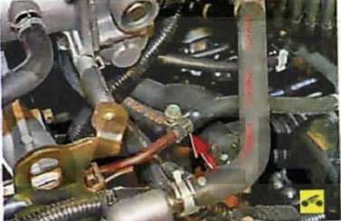
The knock sensor is attached to the top of the cylinder block between cylinders 2 and 3 and detects abnormal vibrations (knock) in the engine.
The sensing element of the knock sensor is a piezoelectric plate. During detonation, voltage pulses are generated at the output of the sensor, which increase with increasing intensity of detonation impacts. The controller, based on a sensor signal, regulates the ignition timing to eliminate detonation fuel flashes.

WARNING:
1. Before removing any components of the fuel injection control system, disconnect the wire from the minus terminal of the battery.
2. Do not start the engine if the cable lugs on the battery are loose.
3. Never disconnect the battery from the car's on-board network when the engine is running.
4. When charging the battery, disconnect it from the car's on-board network.
5. Do not expose the ECU to temperatures above 65 'C in working condition and above 80 'C in non-working (for example, in a drying chamber). It is necessary to remove the computer from the car if this temperature is exceeded.
6. Do not disconnect from the computer and do not attach wires to it when the ignition is on.
7. Before carrying out electric welding work on the car, disconnect the wires from the battery and the wiring harness pads from the computer.
8. Perform all voltage measurements with a digital voltmeter with an internal resistance of at least
9. Electronic components used in the fuel injection system are designed for very low voltage, so they can easily be damaged by electrostatic discharge. To prevent damage to the computer, do not touch its terminals with your hands.
10. To diagnose the engine management system in all cases, a special scanner is required, so if a system malfunction occurs, contact a specialized service .
Source: http://remont-nissan-almera.net/elektrooborudovanie/244-sistema-upravleniya-dvigatelem-osobennosti-konstrukcii.html