![W203/S203/CL203 [2000 - 2004]](/uploads/mercedes-c-klass-w203.jpg)

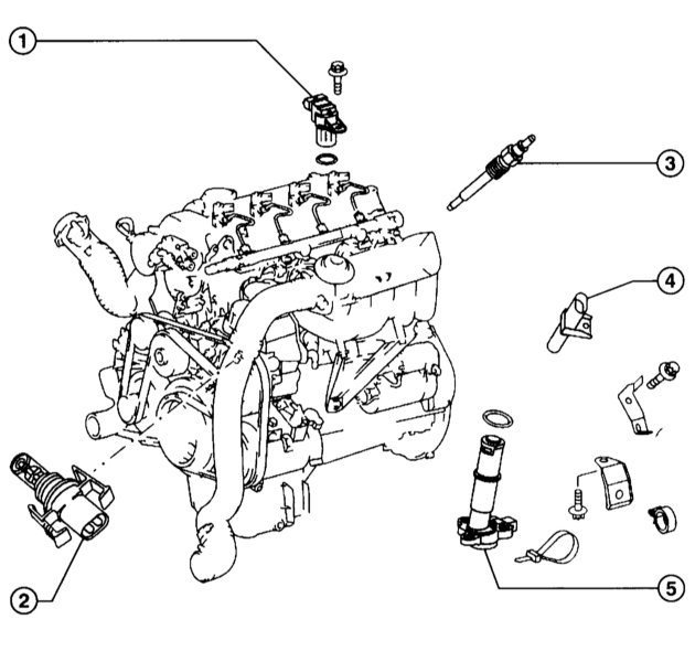
Elements of the diesel fuel injection system:
1 - camshaft position sensor;
2 - a sensitive element of the intake air temperature sensor;
3 - glow plug;
4 - crankshaft position sensor;
5 - oil level indicator sensor, diesel engine.

Functional diagram of common rail fuel injection control
On the example of the 611 engine:
A1 - dashboard;
A1e43 - warning lamp for failures of the electronic power control system (EPC);
B2 / 5 - MAF film sensor;
B4/6 - pressure sensor in the line;
B6 / 1 - camshaft Hall sensor;
B11 / 4 - coolant temperature sensor;
B17 - IAT sensor;
B28 - pressure sensor;
B37 - pedal position sensor;
CAN - data bus;
L5 - CKP sensor;
M55 - inlet port cut-off electric motor;
N2 / 7 - SRS control unit;
N3/9 - CDI control unit;
N10/1 - front SAM unit with relay and fuse box;
N14 / 2 - output stage of the glow plugs;
N15 / 3 - ETC control unit (models with АТ);
N22 - control unit for the push button of the automatic air conditioning system (AAC);
N33/2 - heater fan control unit;
N47 - traction control control unit;
N73 - electronic ignition sensor-switch control unit (EIS);
S40 / 3 - clutch pedal switch (models with manual transmission);
Y31/1 - EGR vacuum transducer;
Y31 / 5 - vacuum transducer for boost pressure control / pressure control damper;
Y74 - pressure regulator valve;
Y75 - electric shut-off valve;
Y76y1-y4 - injectors for cylinders 1-4;
62 - vacuum tank;
63 - control valve;
101 - EGR valve;
104 - vacuum pump;
110 - turbocharger;
110/2 - charge air cooler;
110/10 - vacuum assembly for boost pressure control;
112/1 - filter;
120/1 - oxidation catalytic converter (closer to the engine);
120/2 - oxidation catalytic converter (under floor).
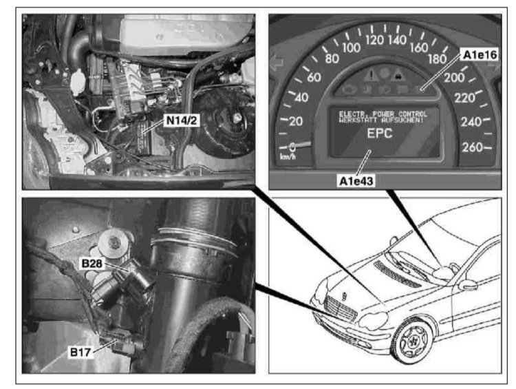

Arrangement of elements of the Common Rail injection control system
On the example of the 611 engine:
A1e16 - preheat control lamp;
A1e43 - EPC failure warning lamp;
B17 - intake air temperature (IAT) sensor;
B28 - pressure sensor;
N14 / 2 - output stage of glow plugs;
N10/1 - front SAM control unit with fuse and relay box;
N3/9 - CDI control unit;
Y31/1 - EGR vacuum transducer;
Y31/5 - Vacuum transducer for pressure/boost control damper

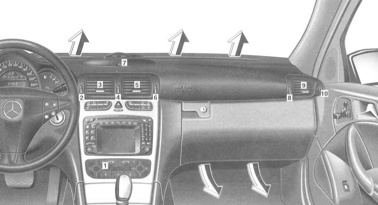
Location of elements of the Common Rail injection control system:
1 - B37 Pedal position sensor;
2 - S40 Tempostat switch;
3 - S40/3 Clutch pedal switch.

HPFP, fuel priming pump, fuel filter and fuel cooler (1 of 2):
1 - Shut-off valve cover, 200CDI/220CDI;
2 - Injector cover, 270CDI;
3 - Fuel cut-off valve, 8Nm;
4 - Intermediate element;
5 - Holder of an intermediate element, 9Nm;
6 - injection pump, 14Nm 7 - pipeline holder;
8 - O-ring;
9 - Fuel pump, 9Nm;
10 - Leash;
11 - O-ring.

High pressure fuel pump, fuel priming pump, fuel filter and fuel cooler (2 of 2):
1 - Fuel filter;
2 - Holder;
3 - Fuel pipeline, fuel priming pump to shut-off valve;
4 — the Holder, the fuel pipeline to the pump of a cooling liquid;
5 - Fuel pipeline;
6 - Hose;
7 - Fuel pipeline, fuel filter to the fuel priming pump;
8 - Fuel pipeline, injection pump to the pressure control valve;
9 - Insulated hose for the drainage pipeline;
10 - Drainage pipeline;
11 - Ring element, drainage pipeline to the fuel filter;
12 - Hollow bolt, drain pipe to the fuel distribution line;
13 - Hose, fuel line to the fuel cooler;
14 - Fuel cooler, 14Nm;
15 - Internal gasket;
16 - Fuel heat exchanger;
17 - Cover;
18 - Fuel filter with holder;
19 - Hose;
20 — Laying bottom;
21 - Fuel heat exchanger housing
Only 2.7L engine:
30 - Fuel pipeline, fuel filter to the fuel priming pump;
31 - Fuel filter;
32 - Pipeline;
33 - O-ring;
34 - Filter element.

vacuum lines. Engine 611.692:
1 - To the right and left pressure transducer;
2 - Working vacuum, atmospheric pressure, control vacuum;
3 - Hose to the turbocharger;
4 - Vacuum box for adjusting the guide vanes of the turbocharger;
5 - Insulated hose;
6 - Pressure converter, left control valve;
7 - Filter left, right;
8 - Protective ring;
9 - Connecting element;
10 - Clamping element;
11 — The holder of the device of recirculation of the fulfilled gases;
12 - Holder on the longitudinal beam;
13 - Connecting hose;
14 - Reservoir;
15 - Pressure converter, boost control.
The diesel fuel system is controlled by the electronic engine management system. It has the following advantages:
- self-diagnosis of the engine management system allows for quick troubleshooting;
- accurate dosing of the amount of injected fuel ensures a reduction in the content of harmful substances in exhaust gases and low fuel consumption;
- regulation of turns of idling and restriction of turns is made automatically.
When a diesel engine is running, clean air is sucked into its cylinders, which is compressed to high pressure. In this case, the air temperature rises to 700°C, which is higher than the ignition temperature of diesel fuel. Fuel is injected into the cylinder with some advance and ignites. Thus, spark plugs are not used to ignite the fuel.
Fuel is supplied by a fuel priming pump at a pressure of 3.5 atm. to the high pressure fuel pump (TNVD). In the injection pump, already at low speeds, a constant compression pressure of over 1300 atm is created.
From the injection pump there is a common fuel distribution line (Common Rail) to the individual cylinders. The common line serves as a pressure accumulator and distributes fuel at constant pressure to the injectors. The amount of injected fuel is dosed with the required accuracy by the engine control unit by means of electromagnetic injectors. If the microprocessor of the engine control unit closes, for example, solenoid valves, fuel injection stops. In other words, pressurization and fuel injection occur independently of each other. The advantage of this is that the injection can take place optimally, depending on the demand and the composition of the exhaust gases, but regardless of the engine speed.
To optimize fuel combustion, the multi-jet nozzles open in two stages. First, a small amount of fuel is pre-injected, which creates favorable conditions for ignition conditions for the main amount of injected fuel. As a result, this leads to a soft and silent combustion of the fuel mixture. When the injector is opened, a small amount of fuel is drawn onto the internal components of the injector, lubricating them, and returns to the fuel tank.
Before fuel enters the fuel priming pump and high pressure fuel pump, it is cleaned in the fuel filter from dirt and water. Therefore, it is important to change the filter regularly as part of the maintenance.
The fuel priming pump and injection pump do not require maintenance. All moving parts of the pumps are lubricated with diesel fuel.
Air is drawn into the engine or comes from the turbocharger and passes through the air filter. The turbocharger compresses air, which then enters the intercooler where it is cooled after being heated by compression in the turbocharger. Cooling contributes to a better filling of the cylinders with forced air, which in turn increases the engine torque and power.
To reduce the proportion of harmful substances in the exhaust gases, diesel engines have a diesel oxidation catalytic converter. At the same time, the recirculation system ensures a significant reduction in the content of nitrogen oxides in the exhaust gases. This is achieved by supplying exhaust gases to the engine intake air, which reduces the oxygen concentration in the air entering the engine cylinders. This results in a delayed ignition and a lower combustion temperature, which ultimately reduces the formation of NOx. The exhaust gas recirculation process must, however, be precisely metered, otherwise the soot content in the exhaust gases will increase. To do this, the amount of air drawn in is determined by the meter, which allows the electronic device to control the recirculation process.
Fuel is injected directly into the combustion chamber.
The engine is controlled by an electronic system similar to that of a gasoline engine. The system controls the operation of the engine by analyzing information from a large number of sensors.
Information about the position of the crankshaft and the speed of rotation of the engine enters the control unit from the crankshaft position sensor. The inductive sensor head is located opposite the flywheel and constantly scans special marks applied to its surface. When the mark passes by the sensor head, it sends a pulse to the control unit. The marks are evenly applied to the surface of the flywheel, but one mark is missing. It should be located 90 ° before the TDC of the first cylinder. When the flywheel passes this point, the sensor does not send a pulse to the control unit. The unit recognizes this pause and accurately determines the TDC moment. The duration of this pause is used to determine the engine speed.
Information about the amount and temperature of the air entering the engine comes from the absolute pressure sensor in the intake manifold and air temperature sensors. The absolute pressure sensor is connected to the pipeline by a vacuum hose and measures the pressure in it. Two air temperature sensors are installed. One is installed before the turbocharger and the other after the intercooler. Temperature and air pressure are used to calculate the exact amount of fuel that needs to be dropped to the injectors.
The coolant temperature sensor measures the temperature and sends the information to the control unit. Analyzing this information, the control unit corrects the composition and injection timing of the fuel mixture, and also controls the cold engine warm-up system.
The brake light switch and brake pedal sensor inform the control unit of the current brake pedal position. When receiving signals from these sensors, the control system immediately switches the engine to idle until it receives a signal from the accelerator pedal position sensor.
The accelerator cable is missing. Instead, an accelerator pedal position sensor is installed. The sensor constantly informs the control unit about the position of the pedal, which, in turn, accurately calculates the injection parameters. The idle speed is also controlled by the control unit and cannot be adjusted manually. Analyzing information from various sensors, the control unit calculates the idle speed, correcting them depending on the load on the engine and its temperature.
The fuel injection system is a direct injection system. In the bottoms of the pistons there are vortex chambers that provide swirling of the fuel entering the combustion chambers.
The heating of a cold engine is controlled by the engine control unit. When the engine is cold, the injection timing is shifted by the control unit. The engine control unit, in turn, controls the operation of the glow plugs. Glow plugs are installed in each cylinder and are switched on before starting the engine, work while cranking the engine with a starter and for some time after starting the engine. Spark plugs make it much easier to start a cold engine. After the ignition is switched on, a lamp lights up on the dashboard, signaling the inclusion of glow plugs. As soon as the lamp goes out, you can start the engine. If the ambient temperature is very low, the spark plugs continue to work for some time after the engine is started. This ensures stable operation of the engine and the reduction of harmful impurities in the exhaust gases.
Due to the good cold start performance of a direct injection engine, pre-heating is only required at temperatures below -10°C.
Fuel passes through the fuel filter. The filter separates the fuel from water and contaminants. Therefore, it is important to remove water from the fuel and replace the filter element in a timely manner.
Operation in winter
With a decrease in the outside air temperature, the fluidity of diesel fuel decreases due to the precipitation of paraffin. Diesel fuel becomes like honey in its fluidity and can clog the filter. For this reason, additives can be added to diesel fuel in winter, which increase the fluidity of the fuel and make it possible to start the engine at an outside air temperature of up to -22°C.
To prevent clogging of the fuel filter at low outside temperatures, the fuel is directed to the heat exchanger.
The article is missing:
- High-quality repair photos
Source: http://auto-knigi.com/model/mb_c/6_3/