![1 generation [2003 - 2007]](/uploads/Mitsubishi_Outlander_I_2003_-_2008_.jpg)
![3 generation [2012 - 2014]](/uploads/3.png)
![XL [2005 - 2012]](/uploads/4d137205da66f_.jpg)


You will need: wrenches "for 12", "for 14", "for 17", a socket head "for 14", pliers, a flat-blade screwdriver, a mounting spatula.
Note:
The work of removing and installing the gearbox is very laborious, therefore, be sure to first make sure that its malfunctions are not caused by other reasons (insufficient oil level, defects in the clutch release drive, loosening of the gearbox, etc.). The gearbox is quite heavy and its shape is not comfortable to hold, so we recommend removing the gearbox with an assistant.
The removal of the gearbox is shown on the example of the automatic transmission (variator) Mitsubishi Outlander XL, as the most difficult.
The main malfunctions, for the elimination of which it is necessary to remove the manual transmission from the car:
- - increased (compared to usual) noise;
- - difficult gear shifting;
- - spontaneous disengagement or fuzzy engagement of gears;
- - oil leakage through seals and gaskets.
The automatic transmission and CVT are removed for almost the same reasons that a manual transmission is removed, except for the need to replace the clutch and flywheel, which in these cases are absent.
The methods for removing and installing manual and automatic transmissions, as well as the variator, are almost the same. The difference lies in the size and number of cables for the transmission control drive, as well as in the presence of an automatic transmission and a variator of hydraulic hoses connecting the gearbox to the cooling radiator.
In addition, the gearbox is removed to replace the clutch, flywheel and rear engine crankshaft oil seal.
Removal and installation of the Mitsubishi Outlander XL gearbox
1. Place the vehicle on a lift or pit.
2. Remove a decorative casing of the engine.
3. Remove the battery.

4. Remove the battery tray.

5. Remove the battery mounting shelf.

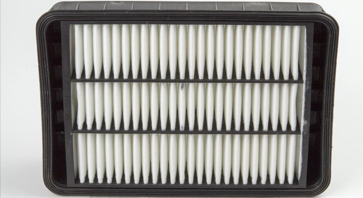
6. Remove the air filter.

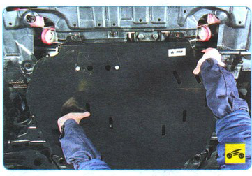
7. Having turned out four bolts and remove protection of a case.

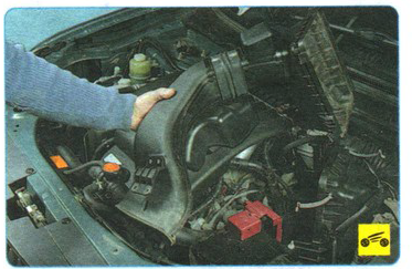
8. Remove the front mudguard of the engine.

9. Drain the working fluid from the variator or automatic transmission (depending on the engine).
10. Drain the coolant.

11. Turn out bolts of fastening of the block of management of the engine and take it aside, without disconnecting blocks of plaits of wires.

12. Wring out a clamp of a collar of fastening of a plait of wires.

13. Remove the cable tie from the bracket.

14. Press the retainer of the input shaft speed sensor wiring harness block.

15. Disconnect the block from the sensor.

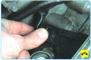
16. Disconnect the output shaft speed sensor harness connector located near the heat exchanger in the same way (shown on the removed engine for clarity).

17. Turn out a bolt of fastening of a "mass" wire to an arm of a tube of system of cooling.

18. Remove the "mass" drive from the gearbox housing.

19. Turn the threaded retainer of the wiring harness block of the automatic transmission valve control unit counterclockwise.

20. Disconnect the connector.

21. Lock the mode switch mechanism.

22. Turn away a nut of fastening of a tip of a cable of a drive of management of an automatic transmission (variator).

23. Disconnect the tip of the cable from the lever.

24. Compress the antennae of the latch of the tip of the drive cable sheath with pliers.
25. Slide the cable back and out of the slot in the bracket.

26. Press the clamp of the block of the wiring harness of the automatic transmission mode switch (variator).

27. Disconnect the block from the switch and take it away from the place of work.
28. Wring out a clamp of a collar of a plait of wires.

29. Remove the clamp with the wiring harness from the automatic transmission bracket.

30. Turn out a bolt of fastening of a plait of wires.

31. Take away an arm together with a plait of wires from a transmission.

32. Squeeze the lugs of the automatic transmission breather hose clamp with pliers, slide the clamp along the hose.

33. Disconnect the hose from the nozzle.

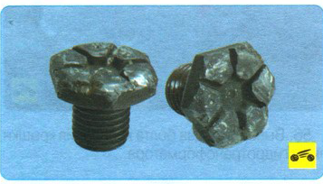
34. Pry off the retainer of the engine splash guard with a screwdriver.


Note:
This is how the pistons for mounting the engine mudguard are located
35. Remove the retainer from the hole.

36. Similarly, remove the remaining clamps and remove the engine mudguard.
37. Squeeze the lugs of the clamp securing the upper hose of the automatic transmission heat exchanger (variator) to the cooling system pipe with pliers.

38. Slide the clamp over the hose and disconnect the hose from the heat exchanger fitting.

39. Similarly, disconnect the lower hose from the heat exchanger pipe.
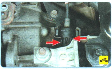
40. Turn out bolts of fastening of an arm of a tube of the heat exchanger.


Note:
This is how the bolts for attaching the heat exchanger tube to the gearbox housing are located.
41. Hang up.

42. Squeeze the lugs of the clamp for fastening the lower hose for cooling the working fluid of the automatic transmission (variator) with pliers, slide the clamp along the hose.

Note:

So on the automatic transmission there are pipes for the cooling system of the working fluid.
43. Disconnect the hose from the nozzle.

44. Similarly, disconnect the upper hose for cooling the working fluid of the automatic transmission (variator).
45. Holding with a wrench, unscrew the nut of the bolt securing the front support of the power unit to the bracket of the protective bar.

46. Remove the bolt securing the front support of the power unit.

47. Turn out two bolts of forward fastening of a protective bar of the power unit to a radiator frame.

48. Turn out a bolt of its back fastening to a crossbar of a forward suspension bracket.

49. Remove the protective bar.

50. Disconnect the rear support of the power unit from the gearbox bracket by unscrewing the nut of the bolt of its fastening to the bracket and removing the bolt.

51. Remove the starter protective shield, disconnect the wire ends from the starter terminals.

52. Remove the starter.

53. Remove the front wheel drives.

54. Remove cardan transmission.

55. Securely support the engine or hang it out with a hoist.
56. Turn out two bolts of fastening of a cover of the hatch of the hydrotransformer.

57. Remove the cover.

58. Turn the crankshaft clockwise by the bolt securing its pulley to a position in which the bolt securing the torque converter to the drive disk will be visible in the hatch.


59. Holding the torque converter drive disc with a mounting blade or a power screwdriver from turning, unscrew the six bolts securing the torque converter to the drive drive.

Note:
Bolts of fastening of the hydrotransformer to a leading disk at each disassembly replace new.
60. Place a secure support under the gearbox or hang it out using a lifting mechanism.
61. Remove the transfer case.

62. Turn out four bolts of the top fastening of a transmission to the block of cylinders.

Note:

This is how the bolts of the upper mounting of the gearbox to the cylinder block are located (for clarity, shown with the coolant distributor removed and the wire harnesses removed).
63. Turn out four bolts of the lower fastening.

64. Turn away three nuts of fastening of an arm of the left support of the power unit.

65. While holding the box, remove the support. Slightly lower the rear of the transaxle just enough so that its studs come out of the left powertrain mounting bracket holes. Move the gearbox as far to the left as possible (the input shaft of the automatic transmission should come out of the torque converter) and remove it from under the car.
66. Before installing a manual transmission, we recommend lubricating the input shaft splines and the outer surface of the clutch release bearing guide bushing with a thin layer of refractory grease.
67. Establish a transmission and all removed details and knots in an order, the return to removal.
68. Check with a special mandrel how the clutch disc is centered. Before attaching the front wheel drives to the gearbox, replace the retaining rings on the splined shank of the inner joints with new ones. Otherwise, it is possible to disconnect the drives from the gearbox while driving.
69. Fill in the working fluid in the automatic transmission (variator).
Source: Third Rome Publishing Manual