![1 generation [2007 - 2010]](/uploads/Nissan_Qashqai_2007-2010_.jpg)

Tools:
- Torx wrench (star) T40
- Large flat screwdriver
- Mounting blade
- Mandrel for centering the driven disk
Parts and consumables:
- Chalk or paint
- Refractory grease
- Driven clutch disc
- Clutch drive
- Pressure plate assembly
- Clutch Release Bearing
- Flywheel
Note:
The main malfunctions, the elimination of which requires the removal and disassembly of the clutch:
- increased (compared to usual) noise when the clutch is engaged;
- jerks during clutch operation;
- incomplete engagement of the clutch (clutch "slips");
- incomplete disengagement of the clutch (clutch "leads").
Useful advice:
If the clutch fails, we recommend replacing all its elements (driven and driving discs, clutch release bearing) at the same time, since replacing the clutch is a laborious job, and the life of undamaged clutch elements has already been reduced. If they are installed again, it may be necessary to replace the clutch again after a relatively short mileage.
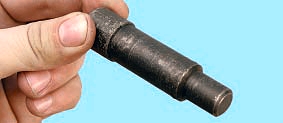
Mandrel for centering the driven disk
1. Remove the front suspension subframe as described here .
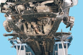
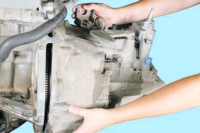
2. Remove the gearbox as described here .
Note:
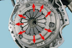
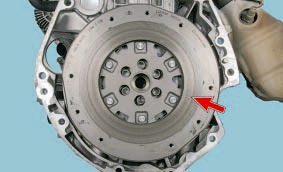
This is how the clutch cover bolts to the engine flywheel are located.
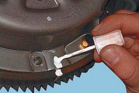
3. If you intend to install the old pressure plate, mark in any way (for example, with paint) the relative position of the disc casing and the flywheel in order to set the pressure plate in its original position (to maintain balance).
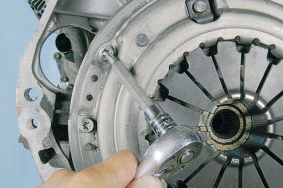
4. While holding the flywheel with a large screwdriver (or mounting blade) from turning, remove the nine bolts securing the clutch pressure plate casing to the flywheel.
Note:
Loosen the tightening of the bolts evenly: each bolt one turn of the wrench, moving from bolt to bolt in diameter.
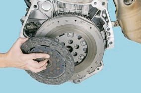
5. Remove the clutch cover assembly with pressure plate and diaphragm spring.
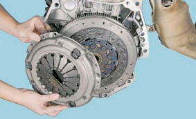
6. Remove the driven disk.
7. Examine a conducted disk of coupling.
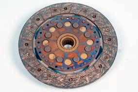
Note:
Cracks on the details of the driven disk are not allowed.
8. Check the degree of wear of the friction linings. If the rivet heads are sunk by less than 0.3 mm, the surface of the friction linings is oily, or the rivet connections are loose, then the driven disk must be replaced.
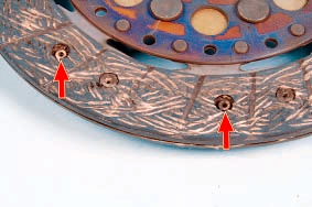
Note:
If the drive plate linings are oily, check the condition of the gearbox input shaft oil seal. It may need to be replaced.
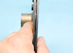
9. Check up beating of a conducted disk if during visual survey its warping is found out. If the runout is greater than 0.5 mm, replace the disc.
10. Inspect the friction surfaces of the flywheel.
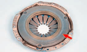
11. Also inspect the surfaces of the pressure plate, paying attention to the absence of deep scratches, scuffs, nicks, obvious signs of wear and overheating. Replace defective units.
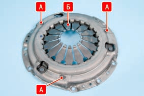
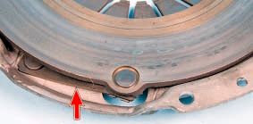
12. When loosening riveted joints A of the casing and pressure plate parts, replace the pressure plate assembly. Visually evaluate the condition of the diaphragm spring B of the pressure plate. The presence of cracks on the Belleville spring is not allowed.
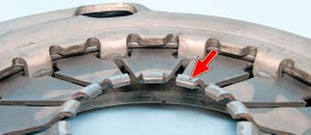
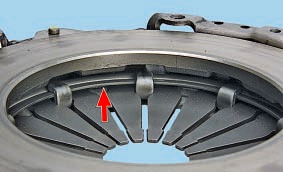
13. The points of contact between the petals of the spring and the clutch release bearing must be in the same plane and not have obvious signs of wear (wear should not exceed 0.8 mm). Otherwise, replace the pressure plate assembly.
14. Inspect the connecting links of the casing and disc. If the links are deformed or broken, replace the pressure plate assembly.
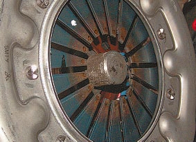
15. Visually assess the condition of the diaphragm spring support rings. Rings must be free of cracks and signs of wear. Otherwise, replace the pressure plate assembly.
16. Before installing the clutch, check the ease of movement of the driven disk along the splines of the input shaft of the gearbox. If necessary, remove the causes of seizing or replace defective parts.
17. Apply high-melting grease to the splines of the driven disc hub.
18. When mounting the clutch, first install the driven disk using a mandrel.
Note:
Install the driven disc so that the protruding part of the disc hub is directed towards the diaphragm spring of the clutch housing.
19. Install the pressure plate cover on the three centering pins and screw in the cover-to-flywheel bolts. Screw the bolts evenly, one turn of the wrench each, alternately moving from bolt to bolt in diameter.
20. Remove the mandrel and install the gearbox.
21. Check and, if necessary, adjust the clutch release drive.
The article is missing:
- High-quality repair photos
- Tool photo
- Photo of parts and consumables
Source: http://nissan-qashqai.dv13.ru/transmissiya/sceplenie/snyatie-i-ustanovka-scepleniya/