![4 generation [2001 - 2005]](/uploads/Volkswagen_Polo_2005_-_2009_.jpg)
![5 generation [2009 - 2015]](/uploads/Volkswagen_Polo_2009-2015_.jpg)

Symptoms: knocking when turning the steering wheel.
Possible Cause: Damaged or deformed tie rods.
Tools and materials: fabric gloves, a set of sockets and wrenches, a set of screwdrivers, a jack, supports for a car, a brush with metal bristles, a caliper, a puller for ball joints, a wire for tying the steering gear to the body, pliers, side cutters, a vice, wire for a garter steering mechanism.
Spare parts and fuels and lubricants: steering rod - 6Q0423803P (other numbers 6Q0423804P, 6Q0423804E);
exhaust system gaskets - 6Q0253115A (other numbers 1J0253115S, 1J0253115L, 1J0253115R, 155253115, 3A0253115, 1H0253115A);
protective cover - 6Q0423831D;
CV joint mounting clamps - N10312301 and 6Q0423933B;
easily penetrating lubricant WD-40 or equivalent;
lubricant SHRUS-4.
Note : To perform work, a lift or viewing hole is required.
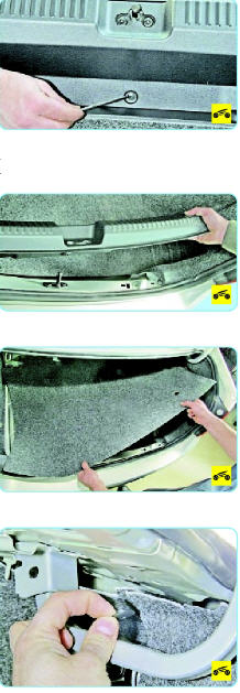
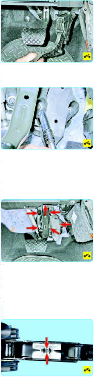
1. Remove the floor covering mounting clip located under the instrument panel on the driver's side.
2. Fold up the floor covering.
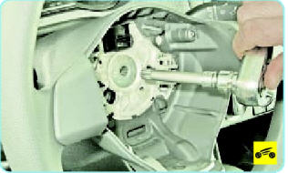
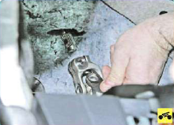
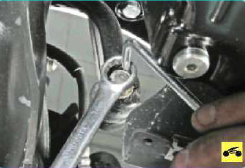
3. Turn off and take a coupling bolt of a terminal connection of an intermediate shaft of a steering column with a shaft gear wheel of the steering mechanism.
4. Disconnect the steering column intermediate shaft from the steering gear shaft.
5. Raise the front of the vehicle using a jack, and then place it on secure and firm stands. Remove the wheel from the side of the tie rod end to be removed.
Note : Remember that loosening and finally tightening the wheel mounting bolts is only allowed with the car on the ground with all wheels.
If fasteners are excessively dirty, clean them with a metal bristled brush, then treat with a light penetrating lubricant such as WD-40 or equivalent.
6. Measure with a vernier caliper and record the length of the free portion of the tie rod end thread.
Note : This operation is necessary in order not to disturb the wheel alignment after assembly.
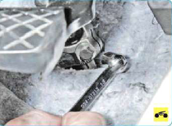
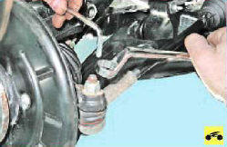
7. Loosen and remove the nut that secures the tie rod end ball pin to the steering knuckle arm while preventing the ball joint pin from turning.
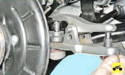
8. Establish the puller intended for a vypressovyvaniye of spherical hinges then press out a finger from an aperture of a rotary fist.
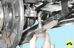
9. Remove the ball joint pin from the steering knuckle hole.
10. Repeat the operations described in paragraphs No. 5-No. 9 on the second side of the car.
11. If the vehicle has been lowered, raise it again with a hoist or hang its front over a viewing ditch.
12. Remove the protective mudguard of the engine.
13. Brake the car with the handbrake, moving it to the highest position.
14. Unscrew and remove the lower mounting nut of the stabilizer strut pivot pin to the stabilizer.
Note : Keep your finger from turning while loosening the nut.
15. Remove your finger from the hole located in the anti-roll bar of the front suspension.
16. Repeat the steps described in paragraphs No. 14 and No. 15 on the other side of the car.
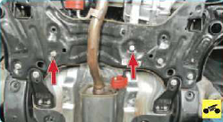
17. Turn off and take out two bolts of an arm of a back pillow of the engine fastening to a check point case.
18. Unscrew and remove the nuts securing the ball joint bolts to the front suspension arms, and then remove the bolts from the arm holes and disconnect the ball joints from the front suspension arms on both sides of the vehicle.
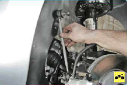
19. Turn off and take out two fixing bolts of the steering mechanism to a cross beam of a forward suspension bracket and fix the steering mechanism, having tied it to a body by means of a wire.
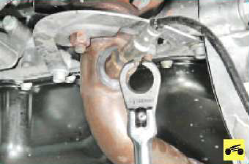
20. Unscrew and remove the lambda probe from the hole in the exhaust pipe of the exhaust system.
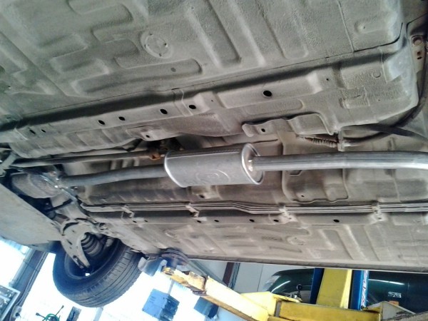
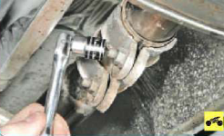
21. Loosen the fixing clamp of the intermediate pipe and the additional muffler of the exhaust system, for which unscrew the nuts and remove the fixing bolts of the clamp.
22. Dismantle the collector and exhaust pipe from the vehicle.
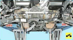
22. Support the cross beam of the front suspension of the car using a jack.
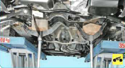
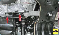
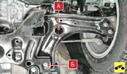
23. Unscrew and remove the bolt (indicated by the letter "A" in the attached photo) of the front and the bolt (indicated by the letter "B" in the attached photo) of the rear fastening of the front suspension cross member to the body. Loosen and remove the front and rear cross member-to-body bolts on the other side of the vehicle in the same manner.
24. Slide the front suspension cross member together with the steering gear and anti-roll bar in the direction of vehicle movement, and then remove it by lowering it down.
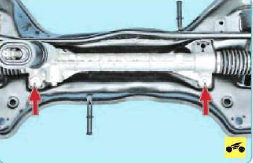
25. Turn off and remove two nuts of fastening bolts of the steering mechanism to a crossbar of a forward suspension bracket, keeping heads of bolts from turning.
26. Remove the steering rack from the front suspension cross member.
27. Remove the outer tie rod ends by unscrewing the first from the second, counting the number of turns.
Note : It is necessary to count in order to, if possible, not violate the wheel alignment angles during assembly.
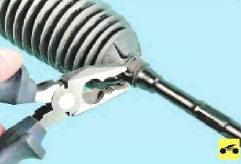
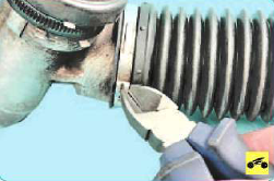
28. Squeeze the bent petals of the mounting collar of the protective cover of the steering rod with the help of pliers.
29. Slide the mounting collar along the tie rod, and then remove it.
30. Cut through the large tie rod boot clamp using side cutters.
31. Remove the clamp.
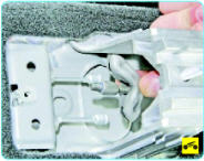
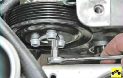
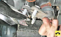
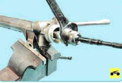
32. Clamp the steering mechanism in a vise as shown in the attached photo.
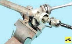
33. Unscrew the steering link from the steering rack and remove the link.
34. With the utmost care, inspect the protective cover of the steering rod.
Note : If tears, cuts and cracks are found on its surface or in the folds of the corrugated part, replace the cover with a new one.
35. Similarly remove and check up the second steering draft.
36. Mount the steering rods and all dismantled parts in reverse order.
Note : When re-assembling the front suspension cross member, tighten the front and rear front suspension cross member mounting bolts to 70 Nm, and then tighten by 90 degrees after installation. The fastening nuts of the ball bearings to the front suspension arms of the vehicle are clamped with a torque of 100 Nm. The steering gear bolts to the front suspension cross member are healed with a torque of 50 Nm, and then turned 90 degrees.
37. Before installing the protective covers of the steering rods, lay the SHRUS-4 lubricant on the working surfaces of the ball joints of the steering rods.
38. Establish new fixing collars of protective covers of steering draughts.
39. Check and, if necessary, adjust the front wheel alignment.
Source: http://www.avtika.ru/qa/1245-snjatie-zamena-ustanovka-rulevoj-tjagi-v-sbore-volkswagen-polo