![5J [restyling] [2010 - 2015]](/uploads/Skoda_Fabia_5J_2010_-_2015_.jpg)
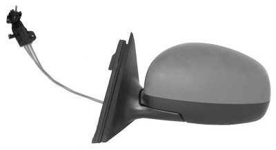
![6Y [restyling] [2002 - 2007]](/uploads/0427389.jpg)

Tools:
- Torx wrench (star) T30
- Phillips screwdriver, medium
- torque wrench
- Pliers
- Knife
- Electric screwdriver
- Screwdriver extension
- Electric hair dryer technical (alternative method)
- Diagnostic OBD scanner VAG COM
Parts and consumables:
- Insulating tape
- Pistons for doors
- Connector for rearview mirror
- Joystick for electric adjustment of exterior rear-view mirrors
- Plug hole from the mirror adjustment knob on the right door
- Mirror glass
- Electric mirror mechanisms
- Wiring
- Onboard power supply central control unit
- Heating elements (alternative method)
- 1.5 mm wire (alternative method)
- Clip-on terminal block (alternative method)
Note:
At the end of the article, an alternative option for installing mirror heating without replacing the control unit is briefly described.
The electric heating of the mirrors is carried out through the central control unit (CU). This article describes the procedure for replacing the CU. The programming of the control unit is carried out by the diagnostic OBD scanner VAG COM.
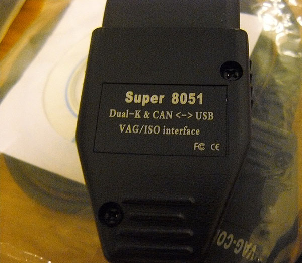
Cord diagnostic OBD scanner VAG COM, which was applied.
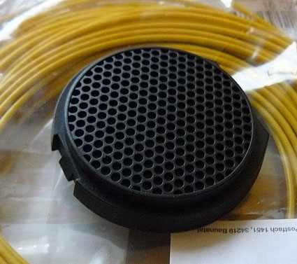
Hole plug from the mirror adjustment knob on the right passenger door (5J0 867 329 A47H).
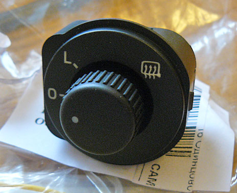
Joystick for electrically adjustable exterior mirrors (5J1 959 565 REH)
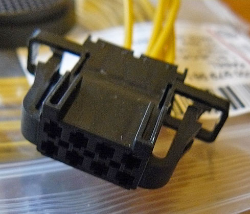
Connector for rear view mirror (3B0 972 724). You need 2 pieces.
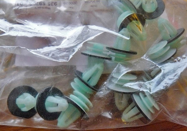
Clips for doors (6Y0 867 260)
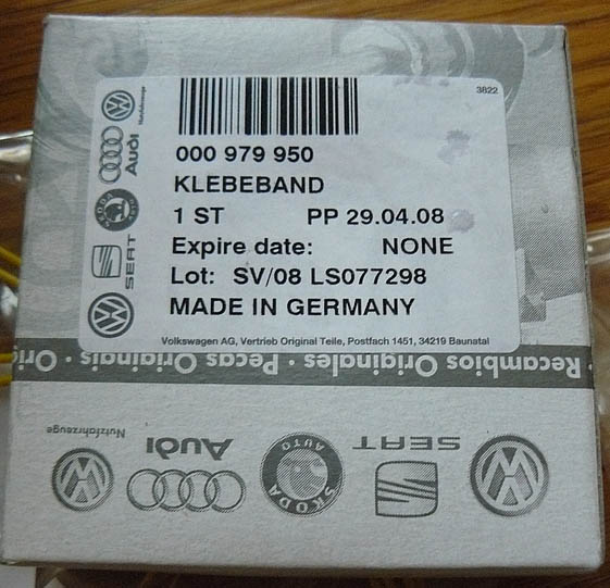
Insulating tape (000 979 950)
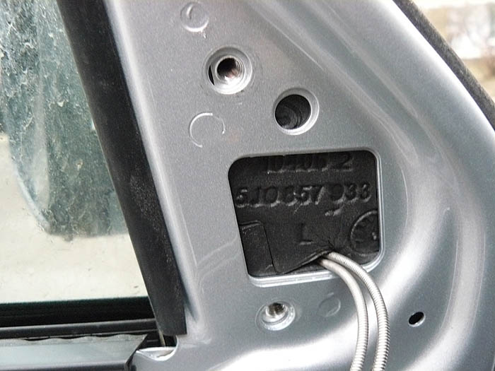
Exterior mirror glass (5J0 857 521 M, 5J0 857 522 M)
Electric mirror mechanisms (5J1 857 507 E, 5J1 857 508 E)
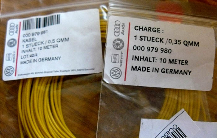
Wiring (000 979 980, 000 979 981)
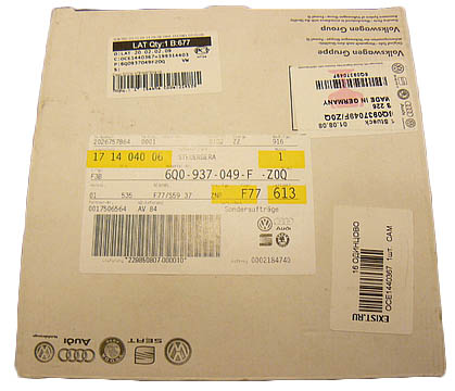
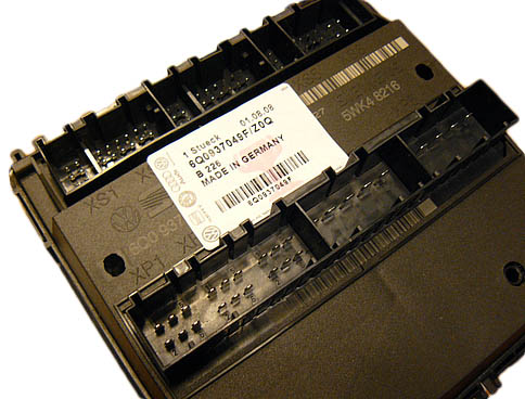
Onboard supply central control unit (6Q0 937 049 FZ0Q)
The main diagram of electrically controlled and heated exterior rear-view mirrors (for vehicles with electrically controlled and heated exterior rear-view mirrors):
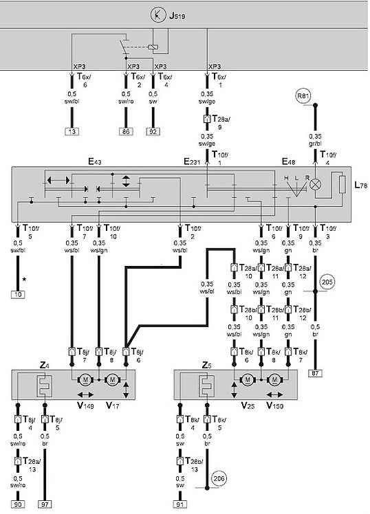
- E43 - switch for adjusting the position of the mirrors;
- E48 - mirror adjustment switch;
- E231 - switch for heating the outside rear-view mirrors;
- J519 - central control unit for the electrical on-board network;
- L78 - lighting switch for adjusting the position of the mirrors;
- T6x - plug connector, 6-pin, on the central control unit for the on-board electrical system (red);
- T8j - plug connector, 8-pin, in the driver's door;
- T8k - Connector, 8-pin, in the front passenger's door;
- T10f - plug connector, 10-pin, on the switch for mirror adjustment;
- T28a - Plug -in connector, 28-pin, on A-pillar left;
- T28b - plug connector, 28-pin, on the A-pillar to the right;
- V17 - motor for adjusting the position of the mirror on the driver's side;
- V25 - motor for adjusting the position of the mirror on the passenger side of the front seat;
- V149 - motor for adjusting the position of the mirror on the driver's side;
- V150 - motor for adjusting the position of the mirror on the passenger side of the front seat;
- Z4 - heating of the outside rear-view mirror on the driver's side;
- Z5 - heated outside rear-view mirror on the passenger side of the front seat;
- 205 - ground connection in the driver's door wiring harness;
- 206 - ground connection in the wiring harness of the passenger door of the front seat;
- R81 - connection 1 (58d) in the driver's door wiring harness.
Note:
To carry out the described process, access to the use of ETKA or ETOS (electronic catalog of spare parts and original accessories) and ELSA (vehicle maintenance program) is critical. They contain all the numbers of contacts and plugs, as well as the principles for connecting contacts.
Order of execution:
1. Disconnect a wire from the plug "-" of the storage battery .
2. Remove the trim on the door handle by pulling it towards you.
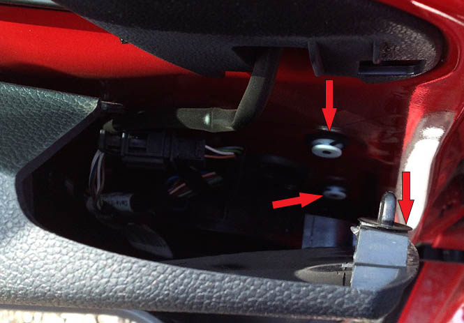
3. Remove two self-tapping screws from the door trim.
4. Loosen the bolts in the door handle using a screwdriver extension. Tightening torque - 4 Nm.
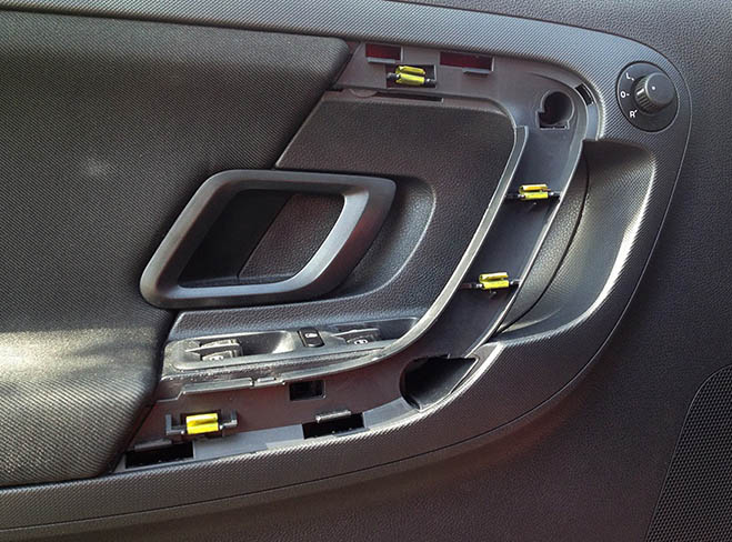
5. Swing back the door trim in the area of the mirror. The door trim will move away from the metal and you will see all the insides. You only need to pull off two white clips and a black one on top, on the right side of the door card.
6. Pull the trim up and down and make sure the white clips are on the door trim and not in the metal of the door. Otherwise, when putting it back on, the clips will not snap into place. If the clips remain in the door, pull them out of the door with pliers and insert them back into the trim.
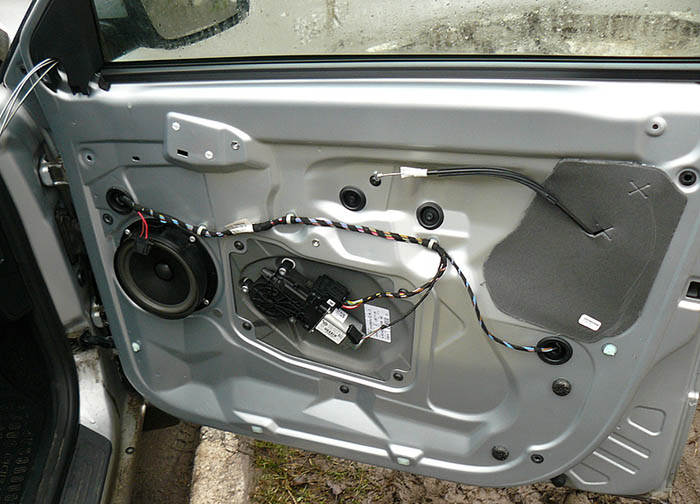
7. Disconnect the trim completely and disconnect the contacts of the immobilizer bulb and the power window connector.
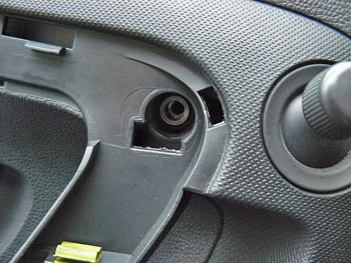
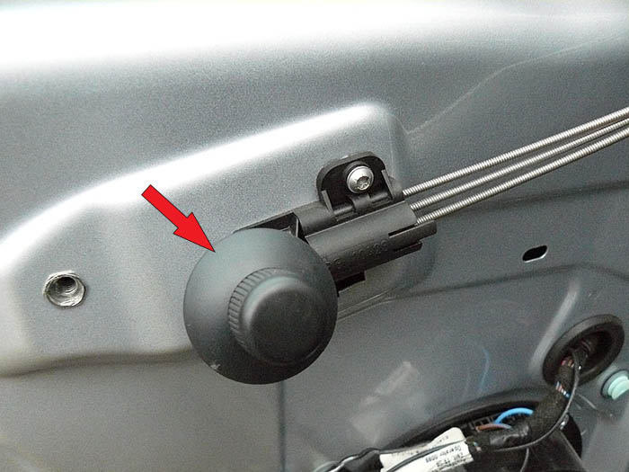
8. Unscrew the joystick for manually adjusting the mirrors.
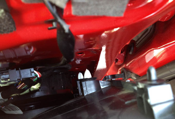
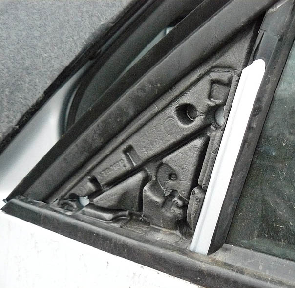
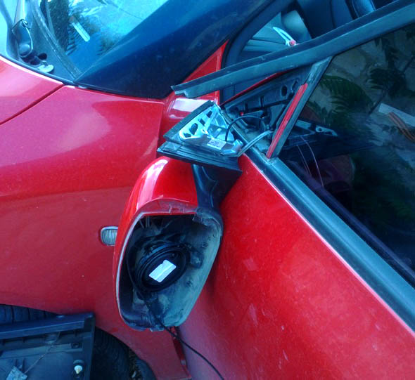
9. Remove the trim from the inside of the mirror by unscrewing 4 bolts. Tightening torque 9 Nm.
10. Having unscrewed screws, remove a rear-view mirror.
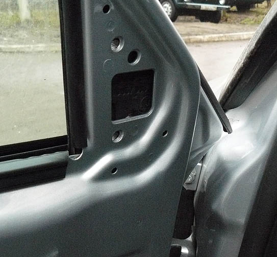
11. Do a similar procedure with the right front door.
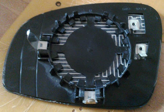
12. After removing the mirrors, they must be disassembled.
The design of the side mirrors.
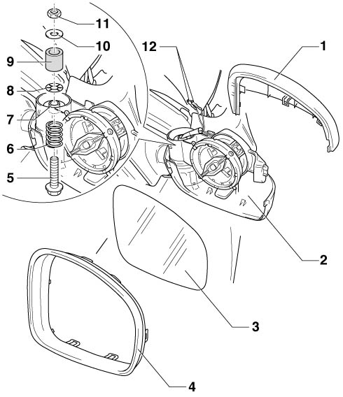
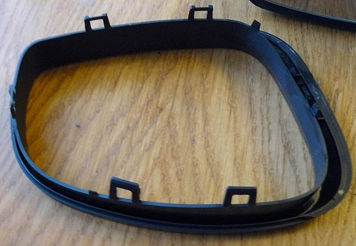
13. Remove frame 4.
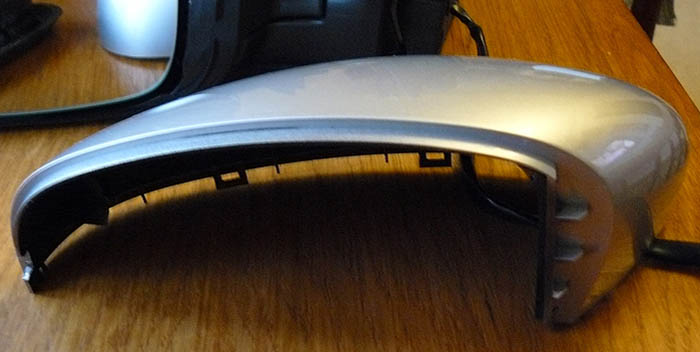
14. Remove the top cover 1.
15. Assemble the mirror with new electrical elements.
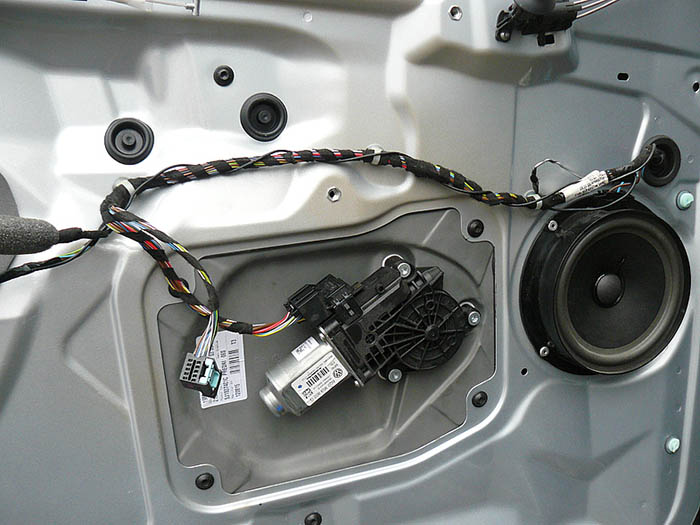
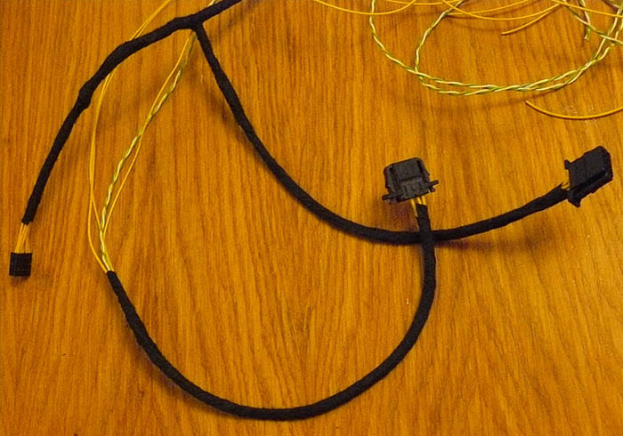
16. Assemble 2 wire harnesses, one for connecting the mirror and adjustment joystick, the second for the right door.
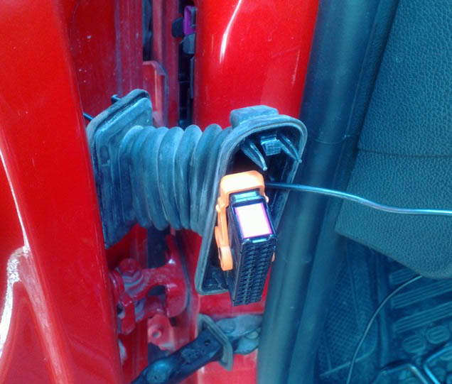
17. Remove the wiring harnesses from the doors. Pull the harness out of the rack, connect from the inside to the door harness, connect to the door lock and close the passenger door with the central lock. Now disconnect everything, the door is closed, the driver's one opens with a key.
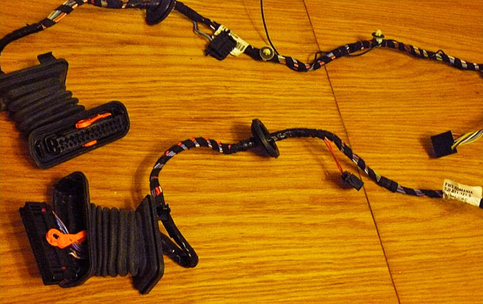
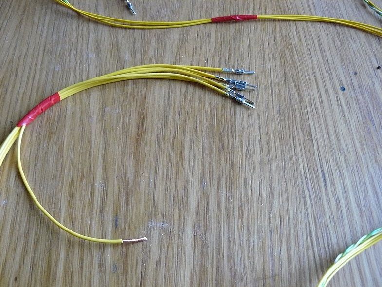
18. Already soldered harness for connecting the racks and the central control unit.
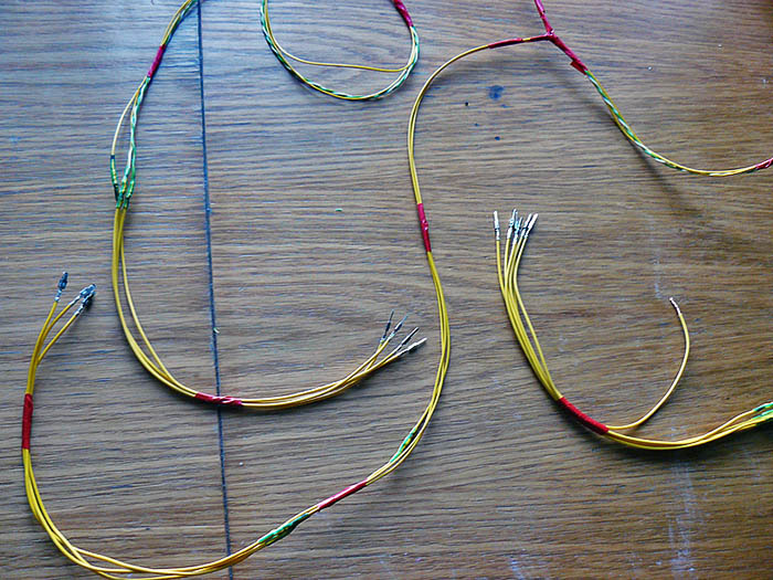
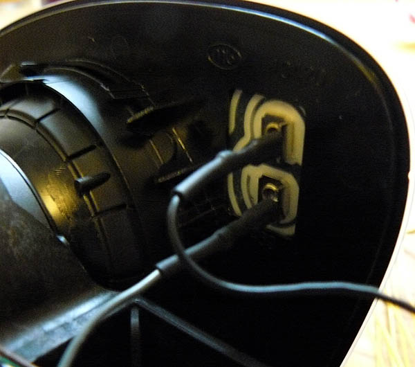
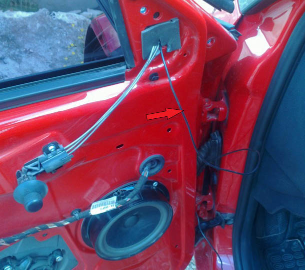
19. Since initially in the car, instead of taking the contact directly in the cabin, the wire is not pulled through the connector in the rack and is connected in the door, so the door wiring harnesses were soldered. The photo shows extra wiring for this.
20. The new central control unit solves with a code starting with 6Q0 instead of the standard 6Q2, solves the following tasks:
- correct display of the door position on Maxi-dot;
- +12 V supply for heated mirrors.
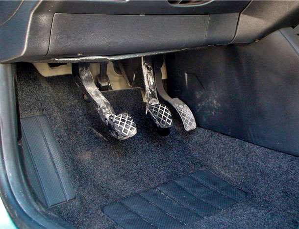
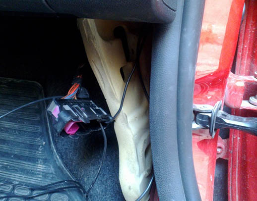
21. The control unit can be placed at the driver's feet under the foam plug above the hood opening handle. You need to find the latches, bend them, and pull out all the connectors one by one. Insert 3 wires into one of the connectors. The newly installed control unit and Gateway must then be programmed.
22. Establish a mirror and a covering of a door upside-down.
Alternative way to install heated rear view mirrors:
To do this, you need to stretch the wires from the mirrors to the threshold of the driver's door in order to connect the positive contact there to the wire going to the heated rear window.
Required:
- heating elements UNI-6L and UNI-6R, 160x95 mm in size;
- I took the wire with a cross section of 1.5 mm, 9 meters.
Procedure
1. Detach the mirror from the door as described above, also using the diagram above.
2. Remove a door covering as it is described above.
3. Thread the wire inside the door to bring it into the corrugation, and then into the cabin.
4. To push the wire through the connector, you can drill out 2 unused contacts in the door block.
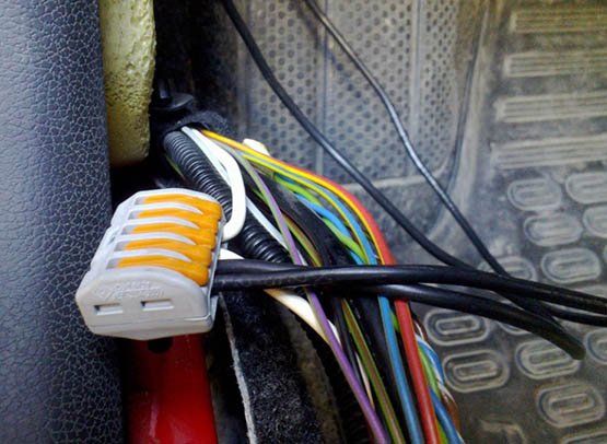
5. Find the wiring harness in the threshold of the driver's door and select the thickest white wire in it, this is the rear window heating wire. For connection, you can use a special terminal block on the clamps.
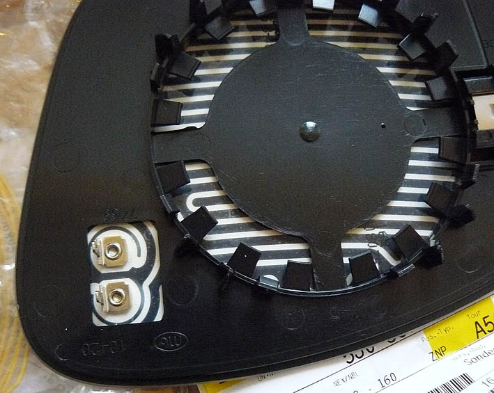
6. Directly for heating, it is necessary to disassemble the mirror, as described above.
7. Then, it is necessary to carefully separate the glass from the plastic. If it doesn’t work out just mechanically, you can use a technical electric hair dryer to heat up the adhesive tape. After that, the glass will be removed easily.
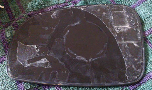
8. Glue the heating element to the mirror. It is necessary to glue in such a way that the contact tracks do not go beyond the edges. If the transparent film sticks out, you need to cut it with a knife.
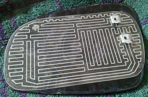
9. Using double-sided tape, glue the mount and heated mirror.
10. Reassemble the mirror and door parts in reverse order.
The article is missing:
- Tool photo
- High-quality repair photos
- Repair Descriptions
Source: http://www.skoda-club.ru; https://www.drive2.ru