![T11 [2005 - 2014]](/uploads/Chery_Tigo_T11_2005_-_2014_.jpg)

Tools:
- rigid support
- Vise
- torque wrench
Parts and consumables:
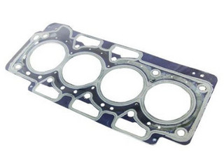
- Timing belt
- Crankshaft pulleys
- Camshaft pulleys
- Tension roller
- intermediate roller
- Automatic tensioner
- Soft overlays
- Pin
- Rigid wire diameter - 2 mm
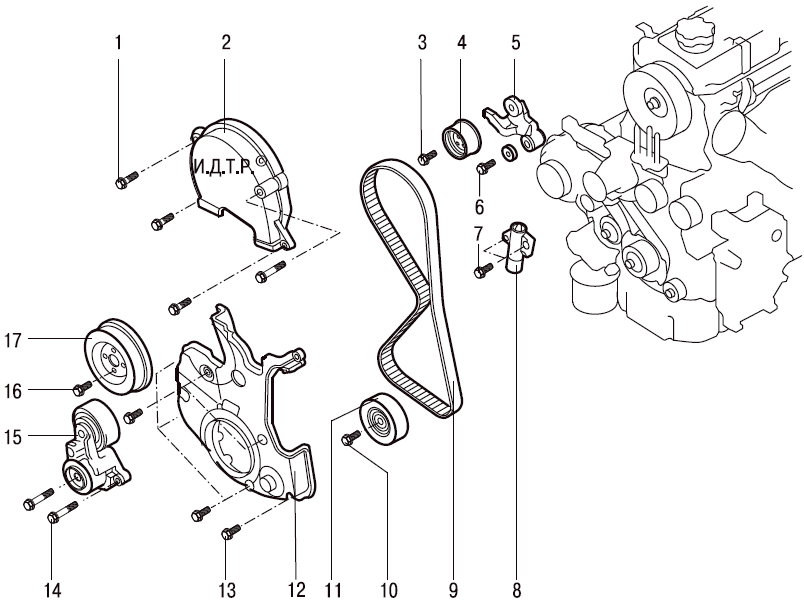
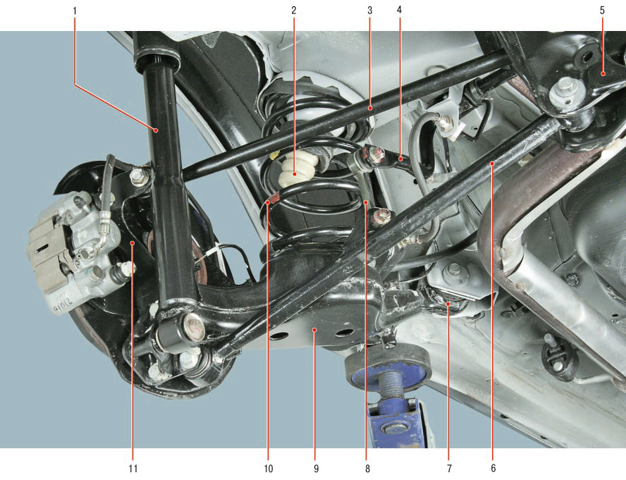
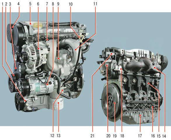
Timing gear drive:
1 – bolts of fastening of the top cover of a drive;
2 – a cover of a drive of the gas-distributing mechanism;
3 – a bolt of fastening of a tension roller;
4 - tension roller;
5 - automatic tensioner lever;
6 – a bolt of an axis of the lever;
7 – a bolt of fastening of a tensioner;
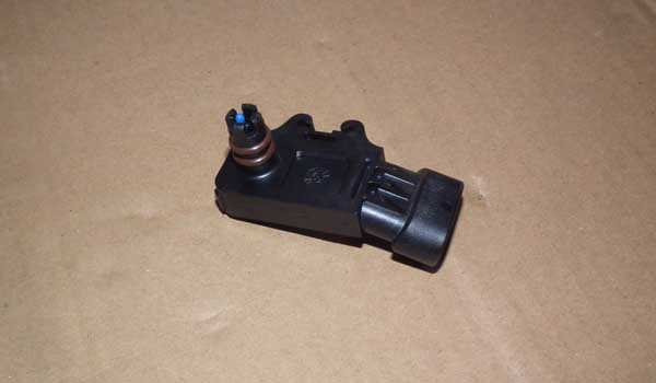
8 - automatic tensioner;
9 - timing belt drive;
10 – a bolt of fastening of an intermediate roller;
11 - intermediate roller;
12 - the bottom cover of the drive;
13 - bolts for fastening the bottom cover of the drive;
14 - bolts for fastening the automatic tensioner of the drive of auxiliary units;
15 - automatic tensioner of the drive of auxiliary units;
16 – a bolt of fastening of a pulley;
17 - water pump pulley.
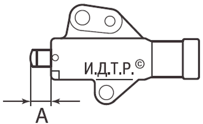
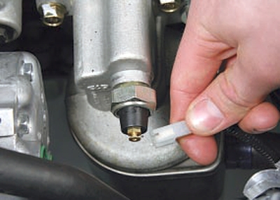
Check the full stroke of the tensioner rod.
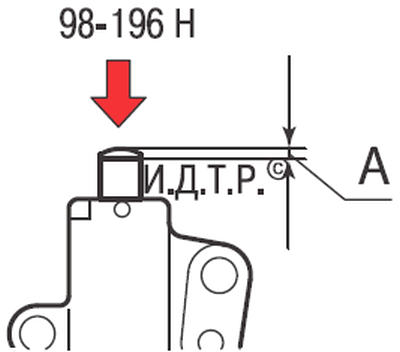
Checking the stroke of the tensioner rod.
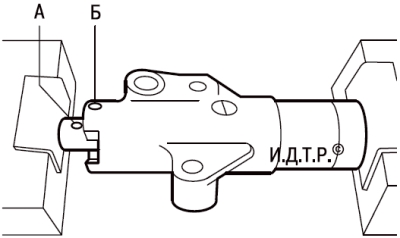
Alignment of holes for fixing the tensioner rod.
Recommendation:
According to the manufacturer's recommendation, the timing belt must be replaced after 40 thousand kilometers or every 4 years of operation (whichever comes first).
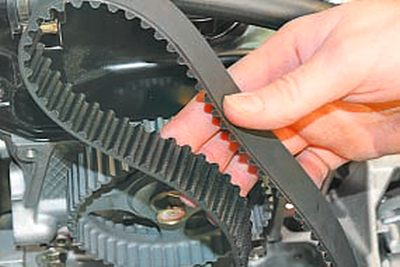
Also replace the belt if, upon inspection, you find:
1 - traces of oil on any surface of the belt;
2 - traces of wear of the serrated surface, cracks, undercuts, folds and delamination of the fabric from the rubber;
3 - cracks, folds, depressions or bulges on the outer surface of the belt;
4 - loosening of the cord threads or delamination on the end surfaces of the belt.
Warning:
A belt with traces of engine oil on any of its surfaces must be replaced, as oil quickly destroys rubber. The cause of oil getting on the belt (usually a violation of the tightness of the crankshaft and camshaft oil seals) must be eliminated immediately.
Note:
Carry out work on a viewing ditch, overpass or, if possible, on a lift.
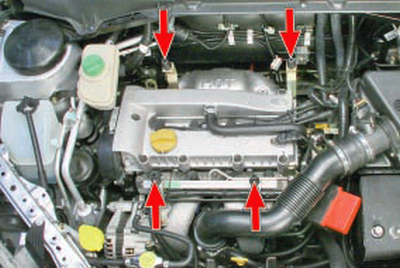
1. Remove the decorative engine cover. (see Removal and installation of a decorative casing of the engine )
2. Remove the accessory drive belt. (Refer to Checking the Tension and Replacing the Engine Accessory Drive Belt with Auto Tensioner )
3. Set the piston of the 1st cylinder to the TDC position of the compression stroke. (see Setting the piston of the first cylinder to the TDC position of the compression stroke )
4. Turn out a bolt of fastening of a pulley of a drive of auxiliary units and remove a pulley from a cranked shaft.
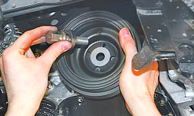
Useful advice:
The accessory drive pulley bolt is overtorqued. In order to fix the crankshaft from turning, turn on V gear and press the brake pedal (this should be done by an assistant).
5. Turn out a bolt 10 (the first drawing) fastenings of an intermediate roller of a belt of a drive of auxiliary units and remove a roller.
6. Turn out bolts 1 and 13 fastenings of the top and bottom covers of a drive of the gas-distributing mechanism and remove covers 2 and 12.
7. Remove two bolts 7 fastening the automatic timing belt tensioner and remove the tensioner 8.
8. Remove the belt 9 from the crankshaft pulley, from the tension 4 and intermediate 11 rollers, the camshaft pulley.
Warning:
After removing the timing belt, it is forbidden to turn the camshafts and crankshafts, as the pistons can damage the valves.
9. Inspect the gear pulleys of the crankshaft and camshaft. Burrs, nicks, chipping of the working surface of the teeth are not allowed. Check the tension and intermediate rollers for mechanical damage and ease of rotation. Replace defective parts if necessary.
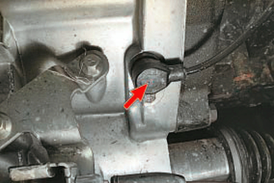
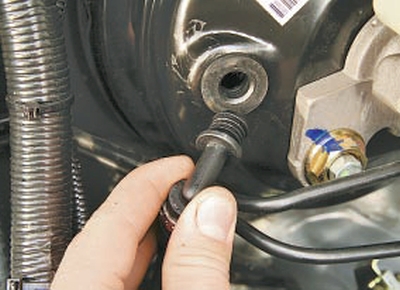
10. Visually check the auto-tensioner for oil leaks. Check the tensioner rod for wear and damage.
11. Measure tensioner rod protrusion. If protrusion A (Fig. Checking the full stroke of the tensioner rod) is less than 12 mm, replace the tensioner.
12. Push the tensioner body into a rigid support and press on the rod (Fig. Checking the working stroke of the tensioner rod.) with a force of 100–200 N. Measure the stroke of the rod A. The stroke of the rod of a serviceable tensioner should be no more than 1 mm. This check can be done with a vise. If the stem sinks easily, replace the tensioner. If compression requires significant effort, the auto-tensioner is good.
13. Slowly squeezing the tensioner in a vice with pads of soft material, sink the rod of the automatic tensioner until hole A (Fig. Combination of holes for fixing the tensioner rod.) in the rod matches hole B in the body, then insert a suitable pin or wire into the aligned holes (rather rigid) with a diameter of 2 mm.
Warning:
If the tensioner is compressed too quickly, it may be bent or damaged.
14. Install the tensioner on the engine and tighten the two bolts of its fastening to a torque of 20–27 Nm.
15. Check the alignment of the crankshaft and camshaft alignment marks and put a new belt on the pulleys in the following order: crankshaft gear pulley, oil pump pulley, intermediate roller, camshaft gear pulley, tension roller.
Note:
If there are arrows on the new belt, they should point in the direction the belt travels when the engine is running when installed.
16. Remove the fixing rod from the tensioner hole.
17. Screw the pulley mounting bolt into the crankshaft shank and turn the crankshaft two turns by the bolt. Check the matching of the alignment marks of the crankshaft and camshaft. If not, reinstall the belt.
18. Check the tension of the timing belt. If the belt is tensioned correctly, the tensioner plunger should protrude from the housing by 7–9 mm.
19. Install all removed parts in the reverse order of removal.
The article is missing:
- Tool photo
- Photo of parts and consumables
- High-quality repair photos
Source: http://chery-tiggo.dv13.ru/osobennosti-konstrukcii-dvigatelej-4g63s4m-i-4g64s4m/zamena-i-regulirovka-natyazheniya-remnya-privoda-gazoraspredelitelnogo-mexanizma/