![G [1998 - 2009]](/uploads/Opel_Astra_II_G_1998_-_2009_.jpg)
![H [2004 - 2011]](/uploads/remont-opel-astra-family.jpg)

The gas distribution mechanism of the Z 16 XER, Z 18 XER, Z 20 LER and Z 20 LEH engines is driven by a toothed rubber reinforced belt, and the Z 14 XEP engine is driven by a chain. Replacing the timing belt is a routine maintenance task and is described in this subsection. The chain is replaced during the current or major repairs of the engine, if necessary, so the work on replacing it is described in Sec. "Features of the design and repair of the engine."
According to the recommendation of the manufacturer of the Opel Astra car, the timing belt must be replaced after 150 thousand kilometers. The timing belt is also replaced if, upon inspection, you find:
Warning
A belt with traces of engine oil on any of its surfaces must be replaced, as oil quickly destroys rubber. The cause of oil getting on the belt (usually a violation of the tightness of the crankshaft and camshaft oil seals) must be eliminated immediately.
Note
Carry out work on a viewing ditch, overpass or, if possible, on a lift.
To replace the timing belt of the Z 16 XER engine, do the following.
You will need: TORX keys E14, E18, T50, hex key “6”, socket head “11”.
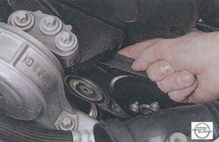
1. Remove the accessory drive belt (see Replacing the accessory drive belt).
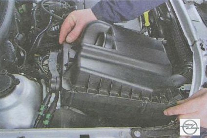
2. For easier access, remove the air filter (see Removing and installing the air filter and air duct).
3. Remove the right front wheel.
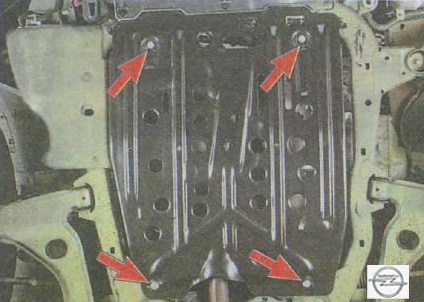
4. Remove the right mudguard of the engine (see Removal and installation of mudguards and engine crankcase protection).
5. Set the piston of the 1st cylinder to the TDC position of the compression stroke (see Setting the piston of the first cylinder to the TDC position of the compression stroke).
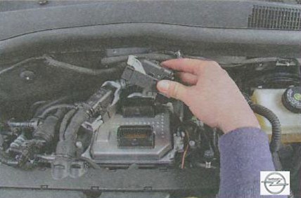
6. Turn out two bolts of fastening of a forward cover of a drive of the gas-distributing mechanism...
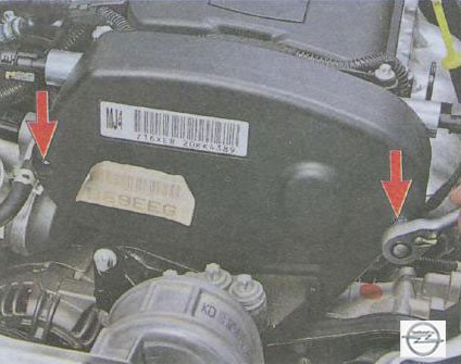
7. ... and remove the cover.
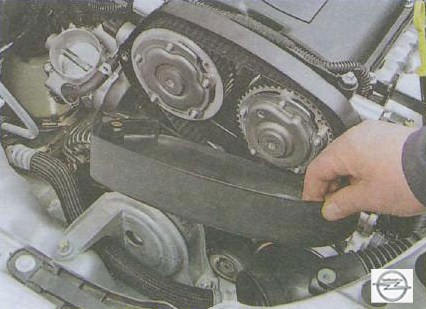
8. If you remove the belt not for replacement, mark with a felt-tip pen the direction of movement of the belt when the engine is running so as not to change this direction when reinstalling.
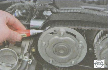
Note
The teeth of the timing belt are run in to the toothed pulleys of the crankshaft and camshafts one-sidedly. Reversing the direction of the belt will cause it to wear faster due to repeated running-in.
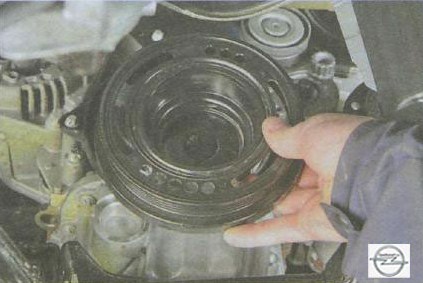
9. Turn out a bolt of fastening of a pulley of a cranked shaft...
10. ... and remove the pulley.
Useful advice
The crankshaft pulley bolt is tightened to a very high torque. In order to fix the crankshaft from turning, turn on V gear and press the brake pedal (this should be done by an assistant).
11. Turn out a bolt of fastening of a tension roller of a belt of a drive of auxiliary units...
12. ... and remove the video.
13. Turn out four bolts of fastening of the bottom cover of a drive of the gas-distributing mechanism...
14. ... and remove the cover.
15. Loosen the intermediate roller mounting bolt, but do not completely unscrew it.
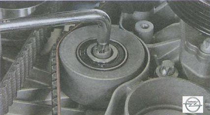
16. Loosen the tension of the timing belt, for which, with key A, turn the roller clockwise until it stops, overcoming the resistance of the roller spring ...
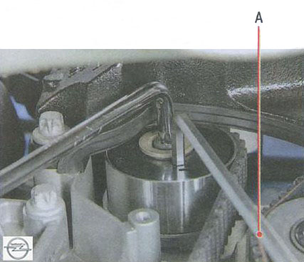
17. ... and then, holding the tension roller in this position, unscrew the bolt securing the intermediate roller and remove it.
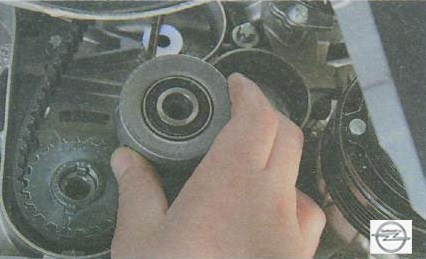
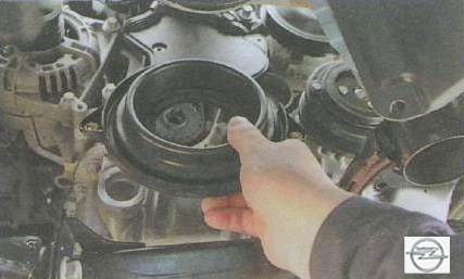
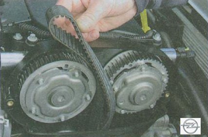
18. Remove the belt from the crankshaft pulley ...
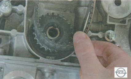
19. ... and remove the timing belt.
Useful advice
Every time you change the timing belt, replace...
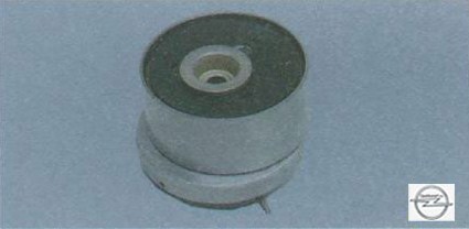
... his tension ...
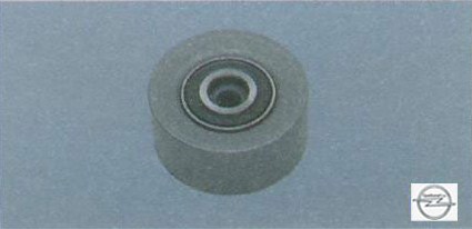
...and intermediate rollers, since their resource has already been reduced and when installing the old rollers after a relatively short period of time, it may be necessary to disassemble them again to replace them. In addition, there is a high risk of destruction of long-running rollers, which will lead to emergency engine failure. The removal of the intermediate roller is described above in this subsection (see paragraphs 15-17) ...
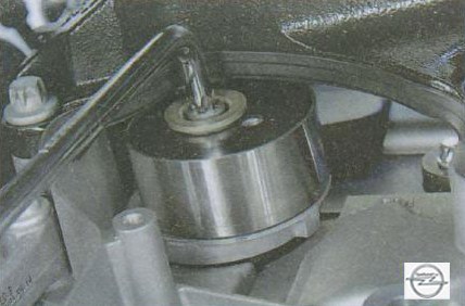
... to remove the tension roller, unscrew the bolt of its fastening.
20. Install the rollers, if they were removed, in the reverse order of removal.
21. Check the coincidence of the alignment marks of the crankshaft and camshafts (see "Setting the piston of the first cylinder to the TDC position of the compression stroke").
22. Put on a belt on a gear pulley of a cranked shaft. Get the drive branch of the belt behind the intermediate roller and, pulling it, put it on the camshaft pulleys. Insert the rear branch of the belt behind the tension roller, after turning it clockwise until it stops (see paragraph 16).
Note
After the action on the tension roller stops, it will take the position necessary for the normal tension of the belt under the action of the spring.
23. Screw the pulley mounting bolt into the crankshaft shank and rotate the crankshaft two turns so that the tension roller provides the nominal belt tension.
24. Check the alignment of the alignment marks of the crankshaft and camshafts. If not, reinstall the belt.
25. Establish all earlier removed details in sequence, return to removal.
To replace the timing belt for the Z 18 XER engine, do the following.
1. Remove the accessory drive belt (see "Replacing the accessory drive belt").
2. For easier access, remove the air filter (see "Removing and installing the air filter and air duct").
3. Remove the right front wheel.
4. Remove the right mudguard of the engine (see "Removal and installation of mudguards and engine crankcase protection").
5. Set the piston of the 1st cylinder to the TDC position of the compression stroke.
6. Turn out three bolts 2 (fig. 1) fastenings of a forward cover 1 of a drive of the gas-distributing mechanism and remove a cover.
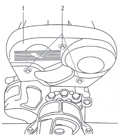
Rice. 1. Removing the front cover of the timing mechanism of the Z 18 XER engine: 1 - the front cover of the timing mechanism; 2 - bolts for fastening the front cover.
7. If you remove the belt not for replacement, mark with a felt-tip pen the direction of movement of the belt when the engine is running so as not to change this direction when reinstalling.
Note
The teeth of the timing belt are run in to the toothed pulleys of the crankshaft and camshafts one-sidedly. Reversing the direction of the belt will cause it to wear faster due to repeated running-in.
8. Remove the tension roller of the auxiliary drive belt by unscrewing bolt A (see "Replacing the auxiliary drive belt", Fig. 1) of its fastening.
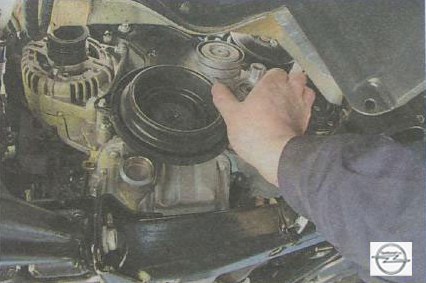
9. Turn out a bolt 3 (fig. 2) fastenings of a pulley 4 of a cranked shaft and remove a pulley.
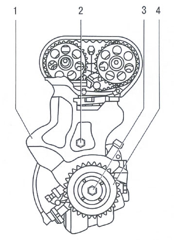
Rice. 2. Removing the crankshaft pulley and the lower cover of the timing mechanism of the Z 18 XER engine: 1 - the lower cover of the timing mechanism; 2 - a bolt of fastening of the lower cover; 3 - a bolt of fastening of a pulley of a cranked shaft; 4 - crankshaft pulley.
10. Turn out a bolt 2 fastenings of the bottom cover 1 gas-distributing mechanism and remove a cover.
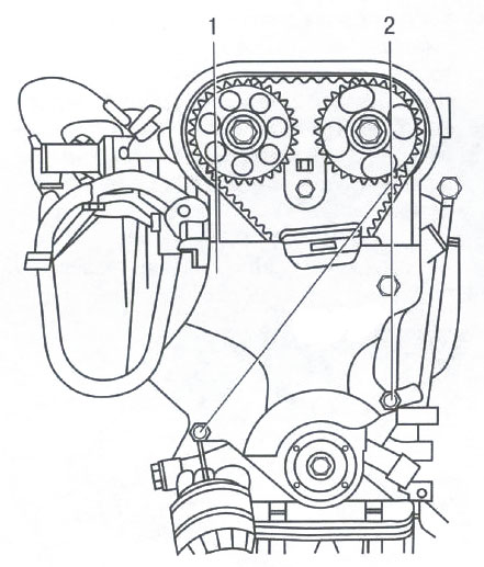
11. Disconnect the phase 2 sensor from the cylinder head (Fig. 3) by unscrewing the two bolts of its fastening.
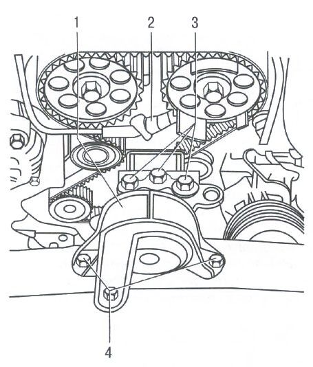
Rice. 3. Removing the phase sensor and the right support of the engine mount Z 18 XER: 1 - the right support of the suspension of the power unit; 2 - phase sensor; 3 - bolts for fastening the right suspension support of the power unit to the engine; 4 - bolts for fastening the right suspension support of the power unit to the body.
12. Support the engine securely.
13. Remove the right support 1 (see Fig. 3) of the suspension of the power unit by unscrewing three bolts 3 of its fastening to the engine and three bolts 4 of fastening to the body.
14. Loosen the tension of the timing belt, for which loosen the bolt 2 (Fig. 4) fastening the tension roller, and turn the roller with the key 3 counterclockwise until the pointer 2 (Fig. 5) of the tensioner is set to the extreme left position. Tighten the idler pulley bolt.

Rice. 4. Loosening the tension of the timing belt of the Z 18 XER engine: 1 - tension roller; 2 - a bolt of fastening of a tension roller; 3 - hex key.
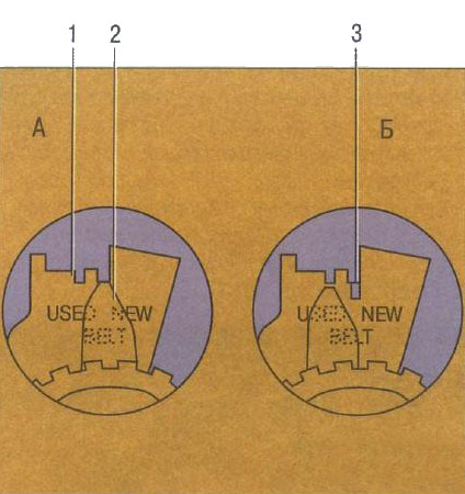
Rice. 5. The pointer of the adjusting unit of the tension roller of the drive of the gas distribution mechanism of the Z 18 XER engine: B - the position of the pointer when installing a new belt; A - the position of the pointer when installing the belt, which was in operation; 1 - mark for tension control when installing a used belt; 2 - pointer of the adjusting unit; 3 - mark for tension control when installing a new belt.
15. Remove the belt from the crankshaft sprocket and remove the timing belt.
Useful advice
Each time you replace the timing belt of the Opel Astra car, replace its tension and intermediate rollers, as well as the water pump (the water pump pulley acts as the second intermediate roller), since their resource has already been reduced and when installing the previous rollers after a relatively short period of time, it may be necessary re-disassembly to replace them. In addition, there is a high risk of destruction of long-running rollers, which will lead to emergency engine failure.
16. Install the rollers and water pump, if they were removed, in the reverse order of removal.
17. Check the coincidence of the alignment marks of the crankshaft and camshafts (see Features of installing the piston of the first cylinder in the TDC position of the compression stroke).
18. Put on a belt on a gear pulley of a cranked shaft. Get the drive branch of the belt behind the intermediate roller and, pulling it, put it on the camshaft pulleys. Pull the driven branch of the belt and put it on the toothed pulley of the water pump, and then put it behind the tension roller.
19. Loosen the bolt 2 (see Fig. 4) fastening the tension roller and turn the roller with the key 3 clockwise until the pointer 2 (see Fig. 5) of the tensioner is set against mark 1 (“USED” - used belt) or 3 ("NEW" - new belt). Tighten the idler pulley bolt.
20. Screw the pulley mounting bolt into the crankshaft shank and rotate the crankshaft two turns so that the belt takes its normal position on the pulleys and rollers.
21. Check the coincidence of the alignment marks of the crankshaft and camshafts. If not, reinstall the belt.
22. Loosen the bolt 2 (see Fig. 4) fastening the tension roller and specify the degree of belt tension (see item 19 in this subsection).
23. Establish all earlier removed details in sequence, return to removal.
The procedure for replacing the timing belt of the Z 20 LER and Z 20 LEH engines is not fundamentally different from the procedure for similar work on the Z 18 XER engine, but has the following differences.
1. Tension roller 1 (Fig. 6) of the auxiliary drive belt is attached with two bolts 2.
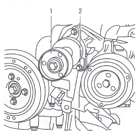
Fig.6. Removing the tension roller of the auxiliary drive belt of the Z 20 LER and Z 20 LEH engines: 1 - tension roller; 2 - bolts for fastening the tension roller.
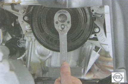
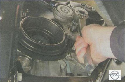
2. Pulley 2 (Fig. 7) of the crankshaft is attached with four bolts 3. To remove it, unscrew these bolts with a wrench 1, holding the crankshaft from turning with a socket head or a spanner wrench 4.
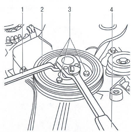
Rice. 7. Removing the crankshaft pulley for Z 20 LER and Z 20 LEH engines: 1.4 - keys; 2 - crankshaft pulley; 3 - bolts for fastening the crankshaft pulley (the fourth bolt is not visible, as it is closed with key 4).
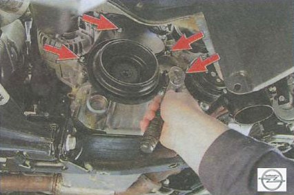
3. To remove the bottom cover 1 (Fig. 8) of the gas distribution mechanism drive, it is necessary to unscrew the two bolts 2 of its fastening.
Rice. 8. Removing the lower cover of the gas distribution mechanism of the Z 20 LER and Z 20 LEH engines: 1 - the lower cover of the gas distribution mechanism; 2 - bolts for fastening the lower cover of the gas distribution mechanism drive.
4. The pointer of the adjusting assembly of the tension roller can be in two versions (Fig. 9).
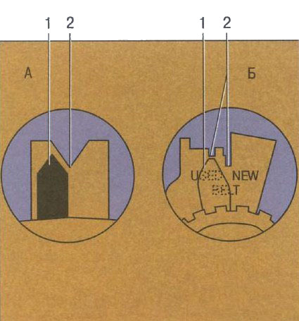
Rice. 9. Pointer of the adjusting unit of the tension roller of the drive of the gas distribution mechanism of the engines Z 20 LER and Z 20 LEH: A, B - versions of the pointer of the adjusting unit of the tension roller; 1 - pointer of the adjusting unit of the tension roller; 2 - labels.
In option A (Fig. 9), to adjust the belt tension, the tension roller is turned clockwise until pointer 1 coincides with the center of mark 2 (a triangular cutout at the base of the adjuster) when installing a new belt or 4 mm to the left of this position when installing a belt, the former in operation. In option B , to adjust the belt tension, the tension roller is turned clockwise until the tensioner pointer is set against the “USED” (used belt) or “NEW” (new belt) mark.
- Source http://www.automnl.com/model/opel_astra_h2/193/