![W203/S203/CL203 [2000 - 2004]](/uploads/mercedes-c-klass-w203.jpg)

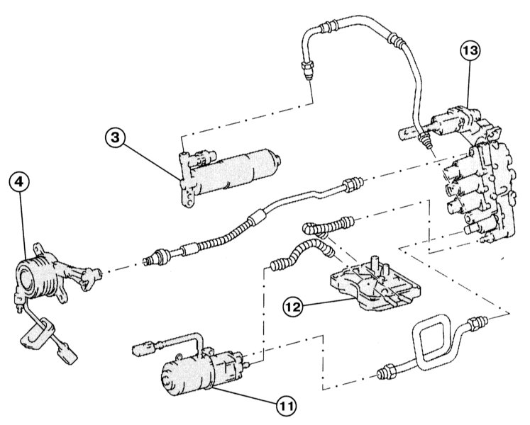
Elements of the hydraulic control of the automated gearbox Sequentronic

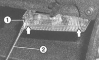
Hinged elements of the automated check point "Sequentronic":
1 - ventilation cover;
2 - ventilation valve;
3 - battery;
4 - clutch release lever;
5 - sealing plug;
6 - front gearbox housing;
7 - gear recognition switch;
8 - speed sensor;
9 - holder of the gear recognition sensor;
10 - gearbox housing;
11 - pump;
12 - tank;
13 - hydraulic block.
Elements of the hydraulic clutch and shift control of the automated gearbox "Sequentronic"
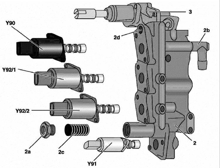
Hydraulic control unit for automatic transmission (Sequentronic):
2 - Valve assembly;
2a - Pressure line connector;
2b - Return line connector;
2c - Oil filter;
2d - Clutch release pressure line connector;
3 - Executive cylinder;
Y90 - Clutch solenoid valve for automatic gear shifting;
Y91 - Solenoid valve for braking automated gearbox with built-in pressure reducing valve;
Y92 / 1 - Solenoid valve switching 1, 3, 5;
Y92/2 - Switching solenoid valve R, 2, 4, 6.
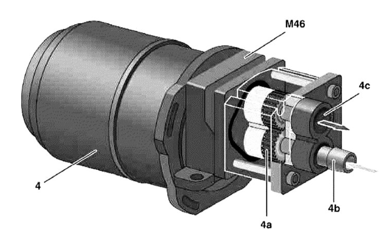
Hydraulic pump for Sequentronic automatic transmission:
4 - Electric motor;
4a - Gear pump;
4b - Oil intake connector;
4c - Pressure line connector;
M46 - Hydraulic pump Sequentronic [ASG].
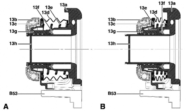
Sequentronic clutch hydraulic drive:
13a - Casing;
13b - Thrust ring;
13c - Balls;
13d - Protective cover;
13e - Preload spring;
13f - Seal;
13g - Working piston;
13h - Coupling;
And — Position of the switched-off coupling;
B - Basic position. Clutch engaged;
B53 - Clutch travel sensor.

Clutch hydraulic operation:
0 - Liquid return channel;
A - Central hydraulic clutch release device;
A1 - Spring;
A2 - Working piston;
B - Valve assembly;
I - Pressure chamber I;
p - Hydraulic pressure;
Y90 - Clutch solenoid valve.
Oil supply to solenoid valves
The oil (Pentosin) pumped by the hydraulic pump is fed through a steel line to the valve assembly, pumped through the oil filter and through the control valve to the clutch, shift and brake solenoid valves.
clutch control
Activation of the clutch solenoid valve is carried out on command from the transmission control unit and provides oil supply through the pressure line connected to the connector in the clutch actuator assembly.
Shift control
Depending on the current driving conditions, the control unit activates the corresponding switching solenoid valve of the valve assembly. The activated valve provides hydraulic pressure to the shift cylinder, which acts on the central shift rod and selects the desired gear through the appropriate connectors in the transmission.
The principle of operation of the hydraulic pump
The electric motor is activated at the command of the control unit and provides a drive to the gear pump connected to the clutch.
The rotation of the gears ensures the suction of the working fluid (oil) through the inlet connector, its compression and supply under pressure through the connector.
The pump also supplies oil to the system pressure reservoir.
The principle of operation of the hydraulic clutch
The working piston under the pressure of hydraulic pressure is shifted forward in the clutch. The thrust ring depresses the disc spring and activates the clutch.
Internal sealing is provided by a sealant.
The protective cover protects the moving surface of the clutch release device from dirt. The preload spring minimizes the initial load of the release bearing drive to reduce background noise.
With the clutch disengaged
The control unit activates a solenoid valve in the valve assembly, which supplies hydraulic pressure to the release device. The working piston moves forward towards the disc spring. The thrust ring is pressed against the disc spring, ensuring its opening.
With the clutch engaged
The valve in the valve assembly is not actuated and the return spring holds it in the base position. As a result, the pressure chamber in the hydraulic squeezer is unloaded, which guarantees communication with the outlet port of the oil reservoir.
The article is missing:
- High-quality repair photos
Source: http://www.auto-knigi.com/model/mb_c/9_2_1/