![1 generation [2010 - 2015]](/uploads/Renault_Duster_2010-2015_.jpg)

Fuel comes from a tank located under the bottom in the rear seat area. The fuel tank, filling pipe and ventilation pipe are made of plastic. The connection of the filling pipe and the ventilation line with the tank branch pipes is non-separable. In the upper part of the filling pipe there is a neck, which is attached to the body. The vent tube is used to remove air squeezed out of the tank when it is refueled. The fuel module, which includes a pump, a fuel pressure reducer, a filter element and a fuel gauge sensor, is located in the fuel tank. For hard fuel cleaning, a mesh filter element is placed at the pump inlet.
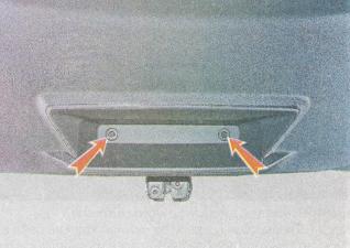
To access the fuel module under the rear seat cushion, a hatch is made in the bottom of the car
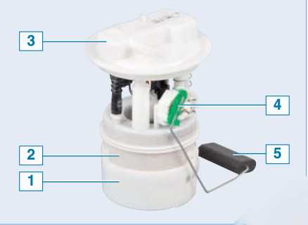
Fuel module of Renault Duster car: 1 - glass; 2 - filter element; 3 - module cover; 4 - fuel gauge sensor; 5 - float
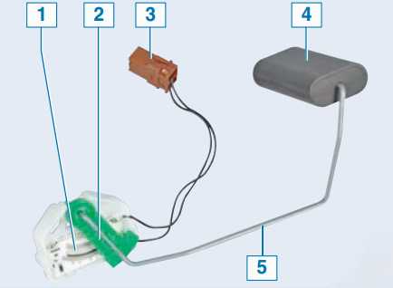
Renault Duster fuel gauge sensor: 1 - resistor; 2 - slider; 3 - block of sensor cables; 4 - float; 5 - float lever
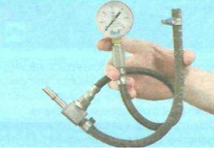
The fuel gauge sensor is attached to the fuel module housing. The fuel gauge sensor is a variable resistor whose resistance depends on the movement of the float. The sensor controls the operation of the fuel level indicator and the minimum fuel level indicator located in the instrument cluster. The fuel pump is located inside the base of the fuel module. The pump is electric, vortex type. It starts at the command of the electronic engine control unit when the ignition is turned on and supplies fuel to the line at a pressure (about 6.0 bar) that exceeds the operating pressure in the fuel rail. The fuel passing through the pump lubricates and cools the pump during operation. Therefore, it is forbidden to turn on the pump even for a short time if there is no fuel in the tank. From the pump, fuel flows through a corrugated plastic tube to the filter and fuel pressure reducer, which are included in the fuel module kit. The fuel filter element (not replaceable) is designed to clean the fuel from mechanical impurities. If the filter is dirty, the fuel module must be replaced. The fuel pressure reducer is a valve that opens when the specified fuel pressure in the line increases and bleeds part of the fuel into the tank. The fuel pressure in the line with the ignition on and the engine off must be about 3.2 bar. The fuel pressure reducer is a valve that opens when the specified fuel pressure in the line increases and bleeds part of the fuel into the tank. The fuel pressure in the line with the ignition on and the engine off must be about 3.2 bar. The fuel pressure reducer is a valve that opens when the specified fuel pressure in the line increases and bleeds part of the fuel into the tank. The fuel pressure in the line with the ignition on and the engine off must be about 3.2 bar.
Renault Duster Fuel Pump
Replacement Fuel Filter Element for Renault Duster 2.0 Engine
If the pressure regulator fails, the fuel module must be replaced. From the base of the filter, fuel enters the module cover through a corrugated plastic tube. The tip of the fuel line passing under the bottom of the vehicle is connected to the outlet fitting of the fuel module cover. The opposite tip of the fuel line in the engine compartment is in contact with the fuel rail fitting (vehicle with 1.6 engine) or with the fuel filter fitting (vehicle with 2.0 engine). The fuel filter element is fixed in the engine compartment on the right side. The opposite fitting of the fuel filter is connected by a tube to the fitting of the fuel rail. In accordance with the vehicle maintenance procedure, the fuel filter element located in the engine compartment must be replaced every 120 thousand kilometers. The fuel rail is a tube made of high-strength heat-resistant plastic, on which nozzles are placed. The ramp is fixed to the intake manifold with two bolts. The fuel rails and nozzles of the 1.6 and 2.0 engines differ from each other.
Fuel under pressure enters the recess of the ramp, and from there through the nozzles - into the channels of the supply pipe. The nozzle is a solenoid valve that injects fuel in nozzle supply passage upon application of a voltage and lockable
fuel rail with injectors of the engine 1,6
fuel rail with injectors of the engine 2,0
influenced by the return spring when de-energized. At the nozzle outlet, a sprayer with four holes is made, through which fuel is injected into the channels of the supply pipe. Manages the operation of the ECU injectors. The injectors are sealed in the rail and inlet pipe with rubber rings and fastened to the rail with metal brackets. If the winding is broken or shorted, the nozzle must be changed.
Engine injector 1.6
Engine injector 2.0
Engine injector nozzle 1.6 Engine
injector nozzle 2.0
Air is supplied to the channels of the engine cylinder head through the air intake, resonator, air filter element, throttle assembly, reservoir and supply hose. The resonator guarantees the absorption of air pressure waves and the reduction of intake noise. The base of the air filter is made of high-strength heat-resistant plastic and is fixed on the rear side of the engine. A replaceable filter element (paper) is adjacent to the air supply opening in the housing, which is closed by a cover. The filter housing has a neck, which
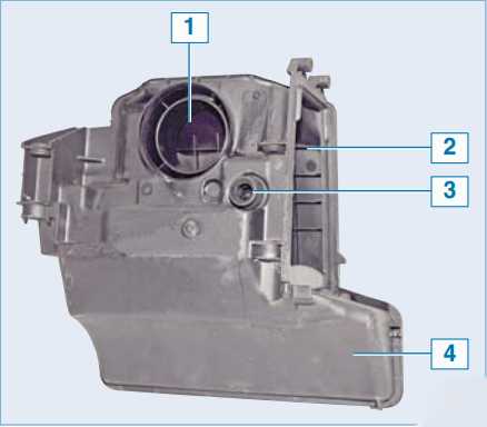
The base of the air filter of a Renault Duster car: 1 - the neck of the connection to the throttle assembly; 2 - air supply hole to the air filter housing; 3 - crankcase gas supply fitting; 4 - the base of the filter is
in contact with the branch pipe of the throttle assembly.
The throttle assembly is located between the air filter housing and the receiver. The throttle assembly is made of aluminum alloy and is the base of the throttle valve, on which the damper control unit is located. The control unit consists of a continuous current motor with a gearbox and 2 damper status sensors
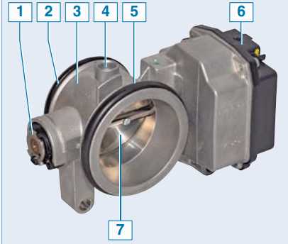
The throttle assembly of a Renault Duster car: 1 - throttle valve axis; 2 - sealing ring of the connecting pipe with the receiver; 3 - base; 4 - hole for connecting the adsorber purge valve line; 5 - sealing ring of the fastening pipe with the air filter housing; 6 - throttle assembly control unit; 7 - throttle valve
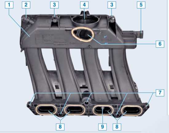
Engine receiver 1.6 of a Renault Duster car: 1 - base; 2 - fitting for connecting the line of the vacuum brake booster; 3 - holes for the rear mounting of the receiver; 4 - hole for fastening with the nozzle of the throttle assembly; 5 - absolute air pressure sensor; 6 - hole not used in this engine design; 7 - holes for the front mounting of the receiver; 8 - air supply channels to the cylinders; 9 - intake air temperature sensor
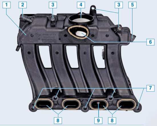
Renault Duster engine receiver 2.0: 1 - base; 2 - fitting for connecting the line of the vacuum brake booster; 3 - holes for the rear mounting of the receiver; 4 - hole for fastening with the nozzle of the throttle assembly; 5 - absolute air pressure sensor; 6 - hole not used in this engine design; 7 - holes for the front mounting of the receiver; 8 - air supply channels to the cylinders; 9 - intake air temperature sensor
The damper opens to the required angle at the signal of the electronic engine control unit (see "Renault Duster car engine control system"). After passing the throttle assembly, the air is supplied to the receiver, made of high-strength heat-resistant plastic. The receiver is fixed on top of the cylinder head cover. From the common cavity of the receiver, air flows through four separate channels to the channels of the supply pipe. In order for the filling of the engine cylinders with air to be identical, the channels of the receiver and the supply pipe are made of approximately the same length. Receivers of engines 1.6 and 2.0 differ slightly from each other - mainly in places of attachment to the cylinder head cover. The fuel vapor recovery system used in the power system includes an adsorber, an adsorber purge solenoid valve and connecting lines.
the tube passing under the bottom of the car, enter the adsorber (located behind the front bumper, in front of the wheel arch of the right wheel), where they are absorbed by the sorbent (activated carbon). An electromagnetic adsorber is located on top of the adsorber
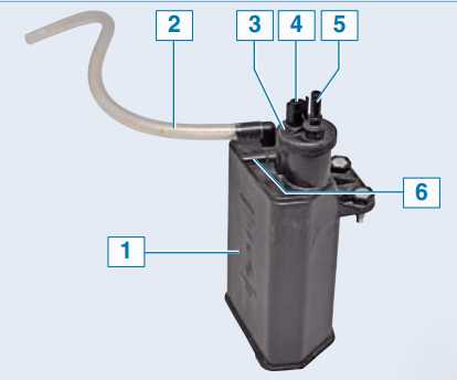
Details of the adsorber of a Renault Duster car: 1 - base; 2 - air supply pipe to the adsorber; 3 - solenoid valve for adsorber purge; 4 - valve electrical plug; 5 - fitting for supplying gasoline vapor to the throttle assembly; 6 - fitting for supplying gasoline vapor from the fuel tank to the adsorber
canister purge valve. The valve is combined with a plastic tube with the throttle space of the throttle assembly. When the engine is stopped, the purge solenoid valve is closed, and in this case the adsorber does not communicate with the throttle assembly. The ECU, controlling the solenoid valve, purges the adsorber after the power unit has worked for a given period of time since the transition to the closed-loop fuel control regulation (the coordinating oxygen sensor must be warmed up to the desired temperature). The valve connects the adsorber chamber with the throttle assembly and the sorbent is purged: gasoline vapors mix with air and enter through the throttle assembly and receiver into the supply hose and further into the engine cylinders. The more air the engine
Source: http://avtorial.ru/Renault/Renault_Duster-45.html