![E140/E150 [2006 - 2010]](/uploads/Toyota_Corolla_E140_2006_-_2010_.jpg)
The car is equipped with two independent braking systems: working and parking. The first, equipped with a hydraulic drive, provides braking when the car is moving, the second brakes the car in the parking lot. The working system is double-circuit, with a diagonal connection of the brakes of the front and rear wheels. One hydraulic circuit provides the operation of the right front and left rear brakes, the other - the left front and right rear.
If one of the circuits of the service braking system fails, another circuit is used to stop the vehicle with sufficient efficiency.
The hydraulic drive includes a master brake cylinder 23 (Figure 1), a vacuum booster 5, a hydroelectronic module 22 of the anti-lock braking system, brakes of the front and rear wheels along with working cylinders and pipelines.
The parking brake system - with a cable drive for the brakes of the rear wheels.
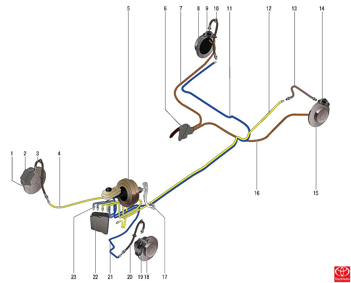
Picture 1
Brake system:
1 - brake disc of the right front wheel;
2 - brake mechanism of the right front wheel;
3 - flexible hose of the brake mechanism of the right front wheel;
4 - pipeline of the brake mechanism of the right front wheel;
5 - vacuum amplifier;
6 - parking brake drive lever;
7,16 - parking brake drive cables;
8 - brake disc of the right rear wheel;
9 - brake mechanism of the right rear wheel;
10 - flexible hose of the brake mechanism of the right rear wheel;
11 - pipeline of the brake mechanism of the right rear wheel;
12 - pipeline of the brake mechanism of the left rear wheel;
13 - flexible hose of the brake mechanism of the left rear wheel;
14 - brake mechanism of the left rear wheel;
15 - brake disc of the left rear wheel;
17 - brake pedal;
18 - brake mechanism of the right front wheel;
19 - brake disc of the brake mechanism of the left front wheel;
20 - flexible hose of the brake mechanism of the left front wheel;
21 - pipeline of the brake mechanism of the left front wheel;
22 - ABS hydroelectronic module;
23 - the main brake cylinder.
The front wheel brakes are disc, with automatic adjustment of the gap between the pads 3 (Figure 3) and the disc 8 with a floating caliper 7. There is a working brake cylinder 4 on the caliper. The shoe guide 6 is bolted to the steering knuckle. The movable bracket is attached with bolts 5 to the guide pins installed in the holes of the guide shoes. The guide pins are lubricated with grease and protected by rubber boots 1. A piston with an O-ring is installed in the cylinder cavity of the movable bracket. The elasticity of this ring maintains an optimal clearance between the pads and the ventilated disc, the surface of which is protected by a brake shield. When braking, the piston, under the action of fluid pressure, presses the inner pad against the disc, by the reaction force, the movable bracket moves on the fingers and the outer block is also pressed against the disc, while the pressing force of the blocks is the same. When the brake is released, the piston is pulled away from the pad due to the elasticity of the sealing ring, as a result of which a small gap forms between the pads and the disc.
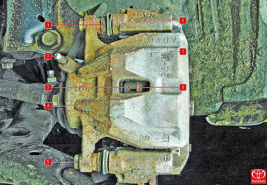
Figure 3
Front wheel brakes:
1 - protective cover for the guide pin;
2 - air release valve;
3 - inner brake shoe;
4 - brake cylinder;
5 - the bolt of the guide pin;
6 - shoe guide;
7 - brake caliper;
8 - brake disc.
The main brake cylinder 8 (Figure 4) of the tandem hydraulic brake drive consists of two separate chambers connected to independent hydraulic circuits. The front camera is connected to the right front and left rear brakes, the rear camera is connected to the left front and right rear.
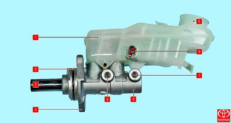
Figure 4
Brake master cylinder with reservoir:
1 - reservoir of the main brake cylinder;
2 - a sealing ring of the main brake cylinder;
3 - piston pusher;
4 - mounting flange;
5 - the neck of the tank;
6 - brake fluid level sensor;
7, 9 - holes for connecting pipelines;
8 - the main brake cylinder.
A tank 1 is installed on the main cylinder, the inner cavity of which is divided by partitions into two compartments. Each compartment feeds one of the chambers of the master brake cylinder.
When you press the brake pedal, the pistons of the master brake cylinder begin to move, the working edges of the cuffs overlap the compensation holes, the chambers and the reservoir are disconnected, and the displacement of the brake fluid begins.
Picture 2
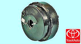
The vacuum booster installed between the pedal mechanism and the main brake cylinder, when braking due to vacuum in the engine intake manifold through the rod and the piston of the first chamber of the main cylinder, creates an additional force proportional to the force from the pedal.
Rear wheel brakes (Figure 5) are disc brakes with automatic clearance adjustment. The brake pads are driven by one hydraulic slave cylinder. The optimum disc-to-pad clearance is maintained in the same way as the front wheel brakes. The working brakes of the rear wheels are combined with the parking brake mechanisms.
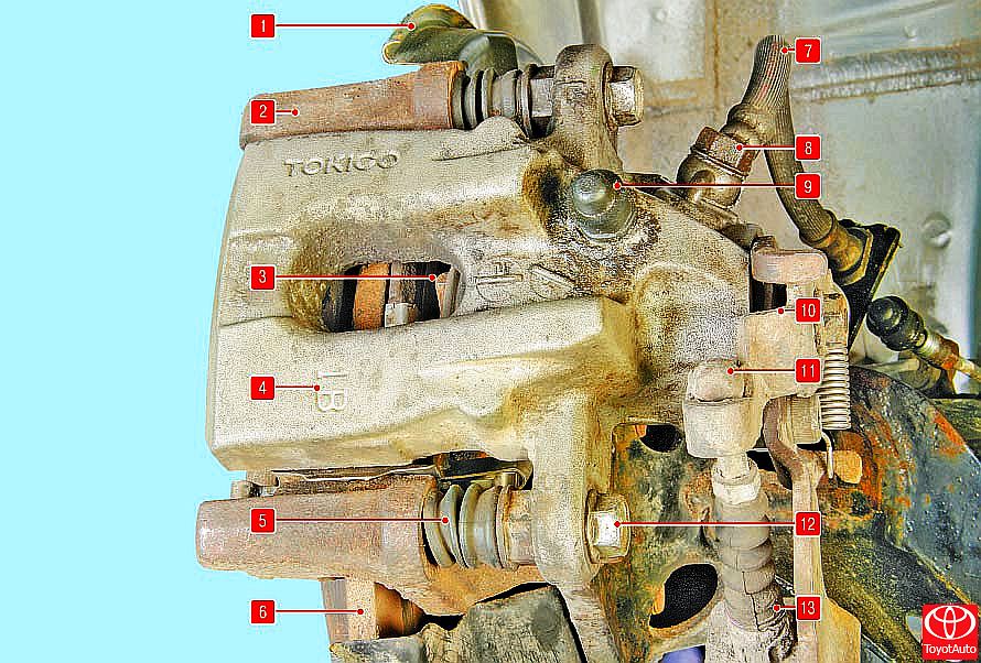
Figure 5
Rear wheel brake:
1 - brake shield;
2 - shoe guide;
3 - brake shoe;
4 - bracket;
5 - protective cover for the guide pin;
6 - brake disc;
7 - brake hose;
8 - bolt fitting of the brake hose;
9 - air release valve;
10 - corner lever of the parking brake;
11 - the tip of the parking brake cable;
12 - guide pin bolt;
13 - cover of the parking brake cable.
The parking brake (Figure 6), which is mechanically actuated, consists of a lever mounted on the base of the body between the front seats, a front cable with an adjuster and an equalizer to which the two rear cables are attached, and release levers installed in the rear wheel brakes. When the parking brake is applied, the corner lever 7 and the rod 3 (actuator assembly), which is connected to the corner lever, rotate under the action of the parking brake cable. At the same time, the input shaft 8 advances the rod, moving the locking ball 4. The screw coupling 9 on the piston, connected to the rod, is also displaced, moving away from the piston 2 and the pads 1 of the brake disc, creating a braking force. The rear ends of the rear cables are connected by angular levers mounted on the input shafts of the parking brake mechanisms. The parking brake lever, fixed between the front seats on the floor tunnel, is equipped with a cable tension adjustment mechanism and an equalizer. The front ends of the rear cables are connected to the equalizer of the tensioning mechanism.
The parking brake does not require any special maintenance. During current repairs, check the degree of wear of its parts, make sure that the spline connection of the angle lever with the input shaft of the mechanism is in good condition. Replace excessively worn parts.
If a sheath or wire break is detected, the cables must be replaced with new ones.
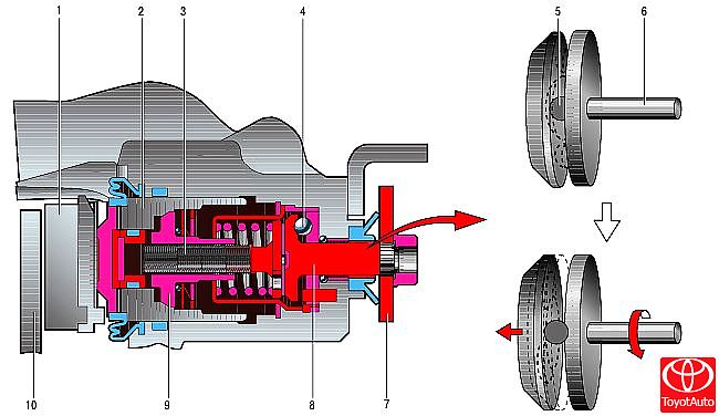
Figure 6
Parking brake operation diagram:
1 - disc brake shoe;
2 - piston;
3 - stock;
4, 5 - locking ball;
6, 8 - input shaft;
7 - corner lever;
9 - screw coupling;
10 - brake disc.
In addition, the car is equipped with electronic systems for increasing active safety: anti-lock braking system (ABS) and brake force distribution (EBD), which are described in Sec. "Security systems".
The hydraulic brake system is integrated into a single unit with metal pipes and hoses. The system is filled with a special brake fluid of at least DOT-4 class, which must be replaced periodically. The procedure for changing the brake fluid and checking the brake system are described below.
USEFUL TIPS:
Some drivers, in an effort to reduce the wear on the parking brake cables, try to use it less often. Such "economy" leads to the opposite result: the cable, rarely moving in the shell, gradually loses its mobility, it gets jammed, as a result the cable breaks. Therefore, use the parking brake whenever necessary.
Source: http://toyotauto.net/corolla/osobennosti-konstrukcii-tormoznoy-sistemy.htm