![1 generation [restyling] [2000 - 2010]](/uploads/Skoda_Octavia_2000_-_2010_.jpg)
![2 generation [2004 - 2008]](/uploads/Skoda_Octavia_2004_-_2012_.jpg)
![3 generation [2013 - 2017]](/uploads/Skoda_Octavia_2013_-_2015_.jpg)
The Skoda Octavia has a compressor-type air conditioning system. The heater units and the evaporator heat exchanger of the Skoda Octavia air conditioner are arranged in one block. The controls for the air conditioning system are located on a panel shared with the heater controls.
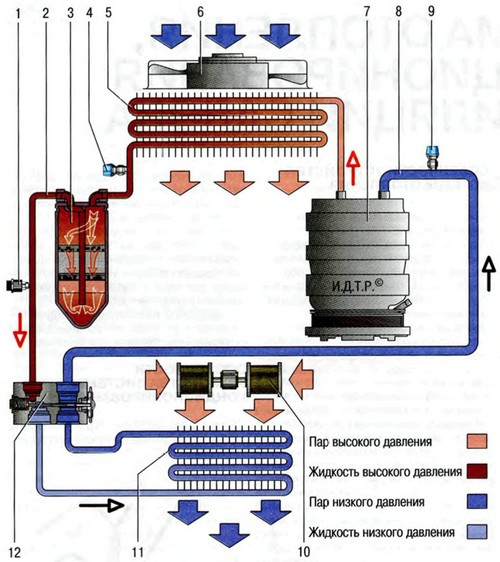
Schematic diagram of the movement of the refrigerant in the air conditioning system:
1. Combined pressure sensor.
2. High pressure pipeline section.
3. Receiver-drier.
4. High pressure line service valve.
5. Condenser (air conditioner radiator).
6. Fan of the condenser and radiator of the cooling system.
7. Air conditioning compressor.
8. Section of the low pressure pipeline.
9. Low pressure line service valve.
10. Heater fan.
11. Evaporator.
12. Thermostatic valve.
 Schematic diagram of the movement of refrigerant in an air conditioning system
The Skoda Octavia air conditioning compressor is installed on the engine block under the generator and is driven by a V-ribbed belt.
The compressor circulates the refrigerant in the system. The compressor shaft is mounted in the front housing cover on bearings and sealed from the side of the drive pulley with an oil seal.
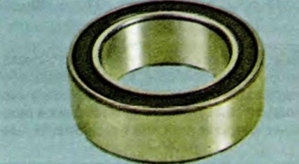
The compressor drive pulley is mounted on a double-row ball bearing and constantly rotates when the engine is running. Torque is transmitted from the pulley to the compressor shaft through the drive disc.
In some versions of the compressor, an emergency pressure relief valve can be installed on the casing. In the event of an increase in pressure in the system due to failure of the pressure sensor or other emergency situations, when the adopted maximum pressure is exceeded, the valve membrane is destroyed and part of the refrigerant is thrown out into the street. As a rule, after this, the tightness of the emergency valve is broken. Therefore, after eliminating the causes that caused the increase in pressure and the discharge of the refrigerant, the valve must be replaced.
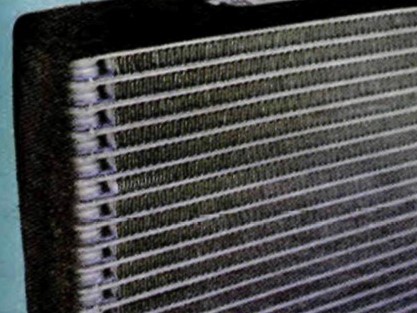
The condenser (air conditioner radiator) of a multi-flow type is located in front of the radiator of the engine cooling system. It is attached with brackets to the radiator frame. The condenser cells are made of flat thin-walled aluminum tubes with internal longitudinal baffles for rigidity and external fins to improve heat transfer. Tanks are aluminum, with flanges for connection of pipelines and a receiver. The tanks are divided into sections along the height, therefore, passing through the condenser, the refrigerant flow changes direction several times. In the condenser, the vapors of the refrigerant compressed by the compressor are condensed, and the heat released in this case is removed to the surrounding air.
When the Skoda Octavia air conditioner is turned on, the engine control unit turns on the power supply circuit for the electric fan of the engine cooling radiator, which improves heat transfer in the condenser and reduces pressure in the air conditioning system.
Useful advice:
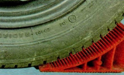
At least once a year, preferably before the start of summer operation, wash the fins A of the condenser honeycombs from adhering dirt, dust and anti-icing agents B. This will improve heat transfer, reduce pressure in the system and increase the service life of the system elements.
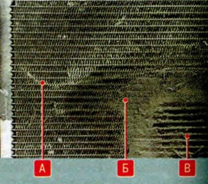
Do not use high pressure water jets to clean the condenser. This can cause damage to the B thin-walled fins. Even with regular washing, the need to replace the condenser occurs much more often than we would like. The fact is that he is the first to take on the flow of anti-icing reagents, dirt and pebbles from the road. And its tube walls are thin ... In most cases, the condenser is damaged by corrosion in the third or fourth year of operation. If the tightness of the condenser is broken as a result of corrosion, then it is more expensive to repair it. Even if the master of argon welding manages to patch the hole, a leak may soon appear elsewhere. By the way, the pressure in the system on hot days can reach up to 25-28 bar.
In addition, the complex structure of the condenser tube should be taken into account: along it is divided into channels by partitions, so it is highly likely that after welding, some of the channels will be blocked. Accordingly, the dissipated power will drop and the operation of the air conditioner will deteriorate, especially in traffic jams and in hot weather.
After each experiment with condenser patching, you will need to pay for removal-installation, welding of the condenser and charging the system with refrigerant. So it is better to immediately install a new condenser. Instead of an expensive original one, it is quite possible to buy a cheaper condenser from authorized spare parts manufacturers.
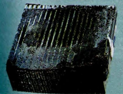
The evaporator is located in the cabin heating and air conditioning unit. The evaporator is made of aluminum tubes with external fins to improve heat transfer. Passing through the evaporator tubes, the siphoning refrigerant actively absorbs heat from the air blowing over the outer finned surface of the tubes. The air is cooled and blown into the vehicle interior by a fan.
Note:
When the air passing through the evaporator is cooled, the water vapor contained in it condenses.
Condensate drains through the drain tube under the bottom of the car. If the ambient humidity is high, a puddle of water may form under the car, which is an indirect sign of the health of the air conditioning system.
Warning:
During the operation of the car, particles of road dust and dirt settle on the outer surface of the evaporator that is wet from condensate.
This layer becomes an excellent environment for life and rapid reproduction of putrefactive bacteria and fungal cultures. Over time, an unpleasant odor develops in the car. It is especially strong when the air conditioner is turned off and in humid weather. In order to minimize the risk of this problem, when buying a new car, it is necessary to carry out preventive treatment of the evaporator with special chemicals, regularly replace the cabin filter and clean the drain tube. If, despite the measures taken, the smell still appears, contact a specialized car air conditioning repair service to disinfect or flush the evaporator. In case of very strong contamination, the evaporator will have to be replaced.
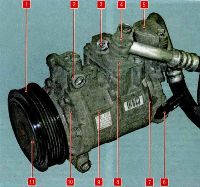
Air conditioning compressor Skoda Octavia:
 Air conditioning compressor Skoda Octavia
1. drive pulley;
2. Compressor mounting eye;
3. Emergency pressure relief valve;
4. Flange for fastening the pipeline of the low pressure line;
5. Flange for fastening the pipeline of the high pressure line;
6. Compressor control valve;
7. Block of petal valves;
8. Top case cover;
9. Housing of the pump part;
10. Front case cover;
11. Leading disk.
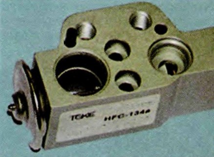
On the side surface of the evaporator there is a flange for mounting a thermostatic valve.
The block-type thermostatic valve is located in the evaporator body. The valve is attached to the pipelines and the evaporator using flange connections. After passing through the throttling hole in the valve body, the liquid refrigerant abruptly reduces its pressure and begins to boil.
A regulating element is installed in the valve body, which changes the flow area of the throttling hole depending on the pressure and temperature of the refrigerant. The adjusting element is adjusted at the factory and cannot be adjusted during operation.
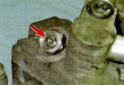
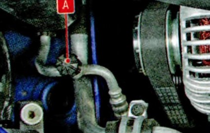
Receiver-drier A is installed on the left condenser tank. The non-separable body of the receiver is made of aluminum alloy.
Pipelines are attached to the body of the receiver with a flange connection. Inside the housing there is a filter element filled with desiccant (silica gel) phases. Passing through the receiver, the liquefied refrigerant is cleaned of possible impurities, dirt and moisture.
Warning:
In case of repair or replacement of air conditioning system elements, if the air conditioning system was in a depressurized state (some components were removed, pipelines were destroyed, etc.), the receiver-dryer must be replaced without fail, after filling the system, the refrigerant will not be dried inside systems, acids can form, which will destroy the parts of the air conditioner from the inside. The receiver-drier is not repairable, it needs to be replaced only as an assembly. When purchasing a new receiver dryer, make sure that the openings of the housing are tightly closed with process plugs. A receiver dryer that has been stored without plugs is unusable, even if it is brand new.
Pipelines connect all elements of the air conditioning system into a single sealed circuit. Pipelines and their fastening flanges are made of aluminum alloys.
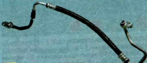
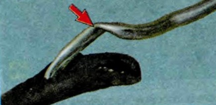
Protect metal sections of pipelines from dents and kinks. Any narrowing of the flow area of the pipeline leads to a decrease in system performance. To connect the mutually moving elements of the system, pipelines in some sections are equipped with flexible inserts made of synthetic materials.
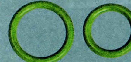
O-rings made of neoprene are installed at the joints of the individual elements of the system. When disconnecting sections of pipelines during.
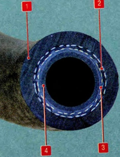
Flexible hose construction:
 Flex hose design
1. Outer protective shell.
2. Fabric cord of the power frame.
3. Plastic sealing layers.
4. Inner oil resistant layer.
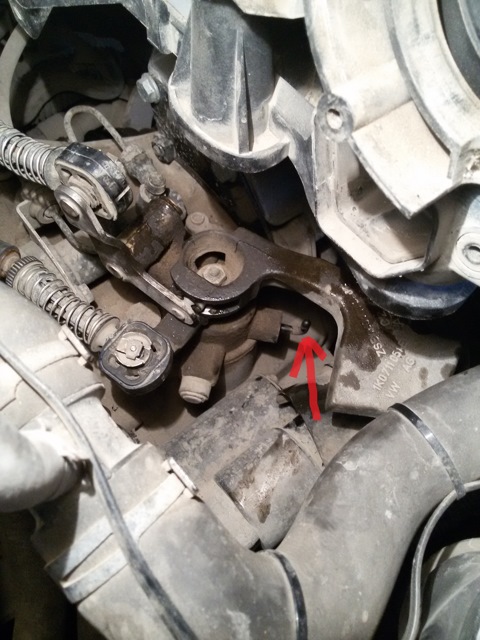
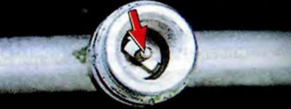
Tighten threaded pipe connections to the recommended torque. Weak or excessively strong tightening leads to deformation of the sealing surfaces and refrigerant leakage. Service valves for connecting diagnostic and filling equipment are located on the pipelines.
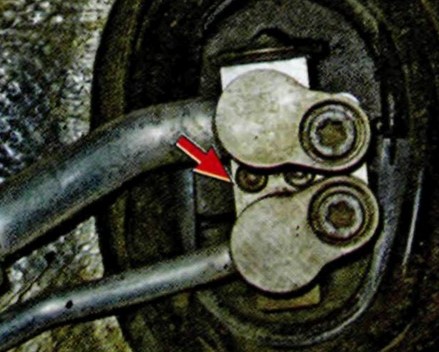
Note:
This is how the service valves of the high A and low B pressure lines are located on the pipelines.
The valves are closed with threaded caps to protect them from dirt.
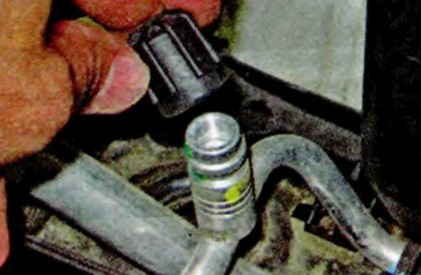
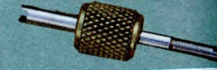
The valves are equipped with spools, similar in design to the spools of the wheel tires, but differing from them in size.
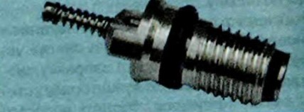
A special key is used to turn the spools in and out.
Warning:
It is forbidden to check the presence of refrigerant in the system by pressing the spools of the service valves, since after such a check the valve spool can completely close and the refrigerant will leak from the system!
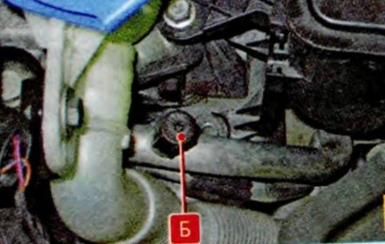
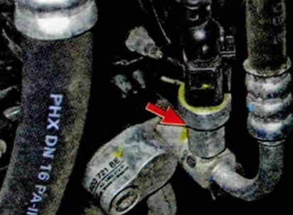
The pressure sensor is installed in the engine compartment on the right side on the section of the pipeline of the high pressure line. According to the sensor signals, the electronic engine control unit turns off the air conditioning compressor in case of depressurization of the systems or an emergency increase in pressure in it in order to protect the compressor from overloads.
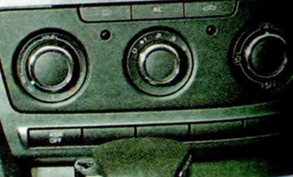
The control panel for the heating and air conditioning system of a Skoda Octavia car is installed on the suction panel console.
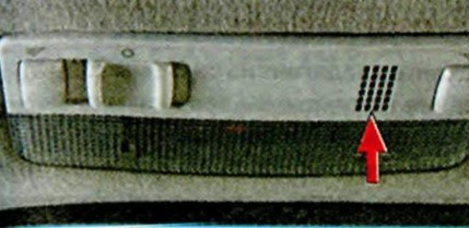
The interior air temperature sensor is installed in the interior lighting dome. To exclude incorrect readings of temperature values due to the influence of heated body elements, the sensor is equipped with a forced airflow system. The system provides an even flow of air from the front of the vehicle through the sensor housing. For normal air movement, keep the sensor housing inlet free of any solid particles or liquids. This is especially true in cases of dry cleaning of the interior. When cleaning the interior with a vacuum cleaner, it is strictly forbidden to bring the suction tip of the vacuum cleaner pipe to the sensor inlet. If the air flow through the sensor housing is obstructed, the normal functioning of the automatic climate control system is disrupted.
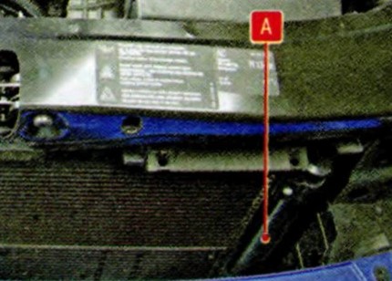
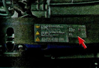
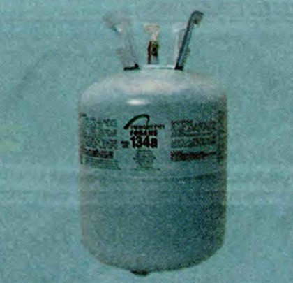
Coolant. An information plate indicating the type and volume of refrigerant used in the system is pasted on the upper surface of the radiator frame. The system is charged with HFC134a (R134a) refrigerant The total charge is (525±25) g. It is strictly forbidden to use other types of refrigerants in the system. Special oil has been added to the refrigerant to lubricate the compressor.
Note:
During the operation of the Skoda Octavia car air conditioner, situations periodically arise when maintenance of the air conditioning system or its repair is required. For this, modern diagnostic and repair equipment is used. The most common situation is the depressurization of the system and the release of refrigerant from it.
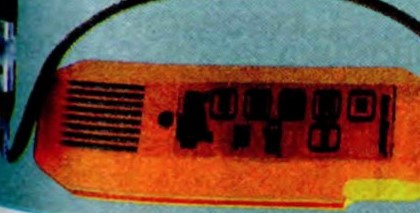
Highly sensitive halogen leak detectors with sound indication are used to detect leaks. In some difficult cases, the so-called method is used. ultraviolet diagnostics of air-conditioning system tightness.
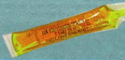
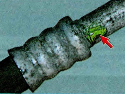
The method consists in the fact that a special dye is introduced into the system in microdoses. In places of microflows, the dye, together with the refrigerant, gradually comes to the outer surface of the system elements.
During the inspection of the system, the dye begins to glow (fluoresce) under the influence of the ultraviolet rays of a special lamp and the refrigerant leaks become visible.
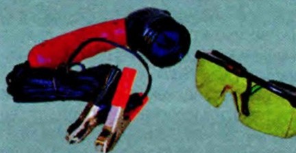
It should be noted that the dye does not have any negative effect on the system. It can be in the refrigerant and circulate through the system for an arbitrarily long time and serve its purpose only when a leak occurs.
After repairing the Skoda Octavia air conditioner, it is necessary to evacuate and fill the system with the appropriate refrigerant. The volume of refueling of the car air conditioner for each car model is individual.
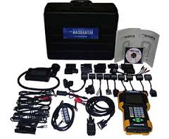
To carry out high-quality refueling of a car air conditioner, you need:
1. Precision gauge blocks with special connection tips.
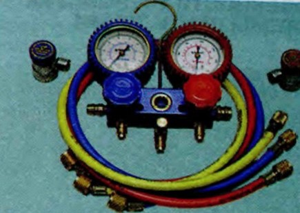
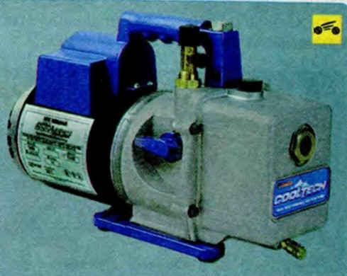
2. Two-stage vacuum pump for complete removal of air and water vapor from the system.
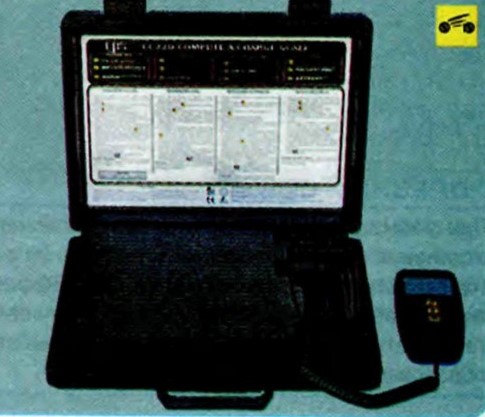
3. High-precision (division value no more than 5 g) scales for dosing the charged refrigerant.
Due to the specific features of the repair of the air conditioning system, this section describes only the work on the removal and installation of individual elements and the system control unit. Work related to charging the system with refrigerant should be carried out in specialized service centers.
Warning:
The air conditioning system is charged with high pressure refrigerant. If liquid refrigerant gets on human skin, it causes severe frostbite, so all work related to the maintenance, repair or dismantling of air conditioning system elements should be carried out, if possible, in specialized service centers equipped with professional technological equipment. When working on your own, take precautions.
Source: http://skoda-octavia2.ru/index.php/sistema-otopleniya-i-ventilyatsii/281-konditsioner-skoda-octavia-osobennosti-ustrojstva.html