![2 generation [2004 - 2008]](/uploads/Ford_Focus_2_2004_-_2008_.jpg)
![3 generation [2011 - 2017]](/uploads/Ford_Focus_3_2011-2015_.jpg)

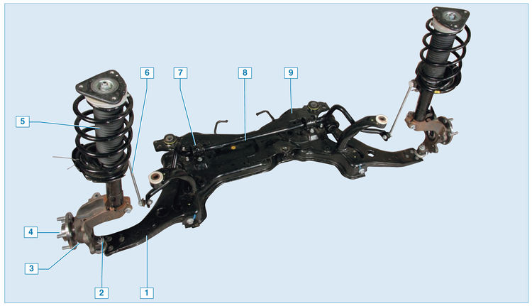
Front suspension :
1 - lever;
2 - ball bearing;
3 - steering knuckle;
4 - hub;
5 - shock absorber;
6 - anti-roll bar;
7 - bracket for attaching the stabilizer bar to the subframe;
8 - bar stabilizer bar;
9 - subframe
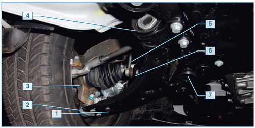
Elements of the front suspension on the car :
1 - lever;
2 - ball bearing;
3 - steering knuckle;
4 - shock absorber;
5 - anti-roll bar;
6 - bar stabilizer bar;
7 - subframe
The front suspension is independent MacPherson type, providing high levels of vehicle smoothness, stability and controllability, with telescopic shock absorber struts that serve to dampen vibrations, absorb shocks and shocks acting on the vehicle through its wheels. The shock absorber struts include elastic elements - springs, which prevent the wheels from separating from the road, providing constant traction and preventing the body from swinging, which accordingly affects the safety and comfort of movement. A hub assembly is attached to the lower part of the shock absorber strut, which is the basis for mounting the wheels and brakes. The hub assembly is connected to the subframe through a ball joint and a transverse lever, and the subframe is connected to the car body. Also, the front suspension is equipped with a stabilizer,
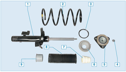
Elements of the shock absorber strut :
1 - telescopic strut;
2 - spring;
3 - thrust bearing;
4 - nut;
5 — the top support of a rack;
6 — the top basic cup of a spring;
7 - compression stroke buffer;
8 — mud-protective cover;
9 - Mudguard adapter sleeve
The basis of the suspension is two shock absorbers that allow the front wheels to move up and down when driving through bumps and at the same time dampen body vibrations. A steering knuckle is attached to the lower part of the strut housing, and a bracket for attaching the anti-roll bar strut is welded to the middle part. A hydraulic gas-filled shock absorber is installed in the rack housing.
A polyurethane foam compression stroke buffer is located on the shock absorber rod, designed to limit the upward travel of the wheel when the car moves over bumps. The helical coil spring of the shock absorber strut with its lower coil rests on the lower cup welded to the strut body, and the upper coil (of reduced diameter) rests on the centering sleeve fixed on the shock absorber rod together with the upper strut support. The upper support of the strut, resting against the cup of the mudguard of the body, due to its elasticity, makes it possible for the strut to swing during the suspension strokes and does not transmit high-frequency vibrations to the body. A thrust bearing located between the upper spring seat and the upper strut seat allows the spring strut to turn with the steer wheel.
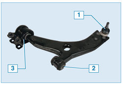
Front suspension arm :
1 - ball joint;
2 - silent block of the front attachment to the subframe;
3 — rear mounting silent block to the subframe
Braking and traction forces during vehicle movement are perceived by the suspension arms connected through ball bearings to the steering knuckles, and through silent blocks to the suspension subframe. The subframe is attached to the spars at four points through silent blocks (pressed into the holes of the subframe).
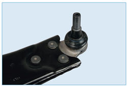
The ball joint housing is riveted to the arm with three rivets, and the ball joint pin is attached to the steering knuckle with a tapered joint .
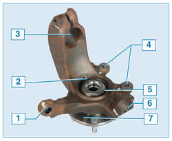
Swivel fist assembly with bearing and hub :
1 - tie-rod end fastening eye;
2 - hole for mounting the wheel speed sensor;
3 - hole for attaching to the shock absorber bracket;
4 — an eye of fastening of a directing brake shoes;
5 - hub bearing;
6 — a hole of fastening of a finger of a spherical support;
7 - hub The hub
bearing, hub and steering knuckle are a non-separable unit, so if it malfunctions, replace the entire unit.
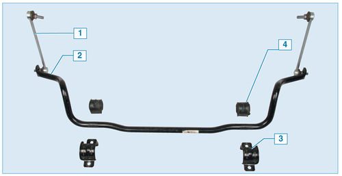
Anti-roll bar :
1 - rack;
2 - rod;
3 - bracket;
4 — a pillow
The bar of the stabilizer of cross-section stability is made of spring steel. The rod in its middle part is attached to the suspension subframe with brackets through two rubber cushions. Both ends of the rod through the ball joints of the struts of the anti-roll bar are attached to the bodies of the shock absorber struts.
To ensure good stability and controllability of the car, the front wheels are set at certain angles relative to the body and suspension elements.
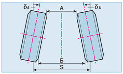
B-A - convergence of the front wheels ;
A and B - the distance (mm) between the flanges of the wheel rims in front and behind ;
δs is the angle of convergence of the front wheels ;
S - track
Toe-in - the angle between the plane of rotation of the wheel and the longitudinal axis of the vehicle. Wheel alignment contributes to the correct position of the steered wheels at various speeds and angles of rotation of the car.
Signs of deviation of the toe angle from the norm: severe sawtooth wear of tires in the transverse direction, increased fuel consumption due to high rolling resistance of the front wheels.
Toe-in is adjusted by rotating the steering rods with the lock nuts of the steering rod ends loosened.
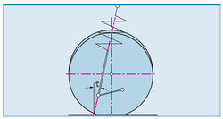
t is the caster angle of the axis of rotation of the wheel
. It contributes to the stabilization of the steered wheels in the direction of rectilinear motion. Symptoms of deviation of the angle from the norm - car pulling to the side when driving, different efforts on the steering wheel in the left and right turns, one-sided wear of the tire tread.
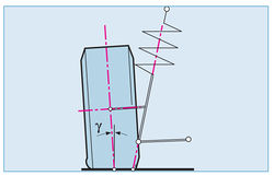
γ - camber angle
Camber - the angle between the plane of rotation of the wheel and the vertical. It contributes to the correct position of the rolling wheel during suspension operation. With a strong deviation of this angle from the norm, the car can be pulled away from rectilinear movement and one-sided wear of the tread.
Only the toe angle is adjustable. The angle of camber and the angle of longitudinal inclination of the axis of rotation of the wheel are set structurally by the geometry of the suspension and body parts. In operation, these angles are not subject to adjustment. It is recommended to check and adjust the wheel alignment angles at a service station. Before adjusting the wheels must be set to the position of the rectilinear movement of the car. The car must be installed on a horizontal platform. Fuel tank, windshield washer reservoir, etc. must be full, the spare wheel is in its original place. There must be no foreign objects in the cabin and trunk.
Wheel alignment angles are given in Table. one.
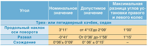
Table 1. Wheel alignment angles
Source: http://wiki.zr.ru/147-2_%D0%A0%D0%B5%D0%BC%D0%BE%D0%BD%D1%82_Ford_Focus_II.