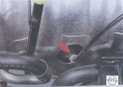
![G [1998 - 2009]](/uploads/Opel_Astra_II_G_1998_-_2009_.jpg)
![H [2004 - 2011]](/uploads/remont-opel-astra-family.jpg)

The engine cooling system is liquid (with forced circulation of liquid), sealed, with an expansion tank.
The system is filled with an ethylene glycol-based liquid (antifreeze) that does not freeze at ambient temperatures down to -40 °C.
Note
The order of replacement of a cooling liquid is described in subsection Replacement of a cooling liquid.
Warnings
It is not recommended to fill the cooling system with water, as antifreeze contains anti-corrosion and anti-foaming additives, as well as additives that prevent scale build-up. Coolant is toxic! Avoid inhalation of vapors and contact with skin.
Timely eliminate the violation of the tightness of the cooling system in order to avoid the ingress of coolant vapor into the vehicle interior during its operation. Your health is more valuable than a new cooling system pipe or a tube of sealant!
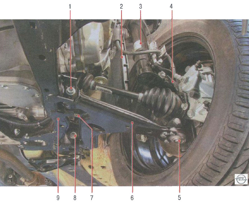
The engine cooling system is shown in fig. 1 using the Z 18 XER engine as an example.
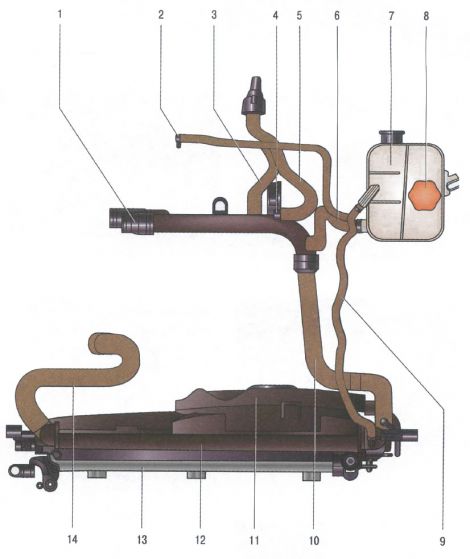
Rice. 1. Elements of the cooling system: 1 - water distribution pipe; 2 - outlet hose for heating the throttle assembly; 3.5- hoses to the heater radiator; 4 - thermostat; 6 - liquid hose of the expansion tank; 7 - expansion tank; 8 - plug of the expansion tank; 9 - steam outlet hose of the expansion tank; 10 - radiator outlet hose; 11 - electric fan; 12 - radiator of the cooling system; 13 - heat exchanger of the air conditioning system; 14 - radiator inlet hose.
The cooling systems of the other engines are arranged almost similarly, the difference lies in the arrangement of the system elements. In addition to the elements shown in the figure, the system includes a cast engine cooling jacket surrounding the cylinder walls in the block, combustion chambers and gas channels in the block head, as well as a passenger compartment heater radiator.
The normal thermal regime of the engine is determined by the temperature of the coolant, which is maintained automatically by a thermostat in the range of 90-100 °C.
Radiator 2 (Fig. 2) with a vertical liquid flow, with a tubular-tape aluminum core and plastic tanks.
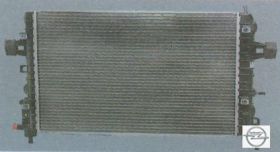
At the bottom of the right tank there is a drain cock 3. The tanks have inlet and outlet hose pipes to the engine water jacket, as well as a hose pipe connecting the radiator to the expansion tank.
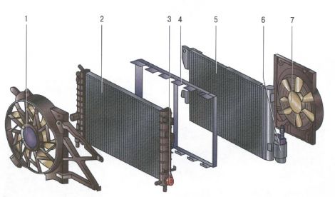
Rice. 2. Radiator, heat exchanger and electric fans of the cooling and air conditioning system: 1 - electric fan of the cooling system; 2 - radiator of the cooling system; 3 - valve for draining the coolant; 4 - radiator connector; 5 - heat exchanger of the air conditioning system; 6 - condenser of the air conditioning system; 7 - electric fan of the air conditioning system.
Expansion tank 7 (see Fig. 1) serves to compensate for the changing volume of the coolant depending on its temperature.
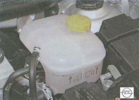
The tank is made of translucent plastic. Its walls are labeled "KALT / COLD" to control the level of the coolant, a filler neck is located on top, hermetically sealed with a plastic stopper 8 with two valves inside it (inlet and outlet), assembled in a single block. The exhaust valve opens at a pressure of 140-150 kPa (1.4-1.5 kgf / cm 2 ), providing an increase in the temperature at which the coolant begins to boil and preventing intense vaporization. When the liquid is cooled, its volume decreases and a vacuum is created in the system. The inlet valve in the plug opens at a vacuum of about 3 kPa (0.03 kgf / cm 2 ) and lets air into the expansion tank.
Note
The serviceability of the plug valves is very important for the normal operation of the cooling system, but often when problems arise (coolant boils, etc.), motorists pay attention only to the operation of the thermostat, forgetting to check the valves. Leakage of the exhaust valve leads to a decrease in the boiling point of the coolant, and its jamming in the closed state leads to an emergency increase in pressure in the system, which can cause damage to the radiator and hoses.
A centrifugal-type water pump provides forced circulation of liquid in the cooling system, is installed on the front surface of the cylinder block and is driven by a V-ribbed belt for driving auxiliary units (Z 14 XEP and Z 18 XER engines) or a timing belt for timing gear (Z 18 XER, Z engines). 20 LER and Z 20 LEH). The pump has sealed bearings that do not require relubrication. The pump cannot be repaired; in case of failure (liquid leakage or damage to the bearings), it is replaced as an assembly.

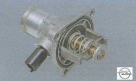
Thermostat 4 (see Fig. 1) with a solid temperature-sensitive filler maintains the normal operating temperature of the coolant and reduces the engine warm-up time. It is mounted in an aluminum housing on the thermostat module. At a coolant temperature of up to 80 ° C, the thermostat is completely closed and the liquid circulates through a small circuit, bypassing the radiator, which accelerates engine warm-up. At a temperature of 80 °C, the thermostat starts to open, and at 95 °C it comes off completely, providing fluid circulation through the radiator.
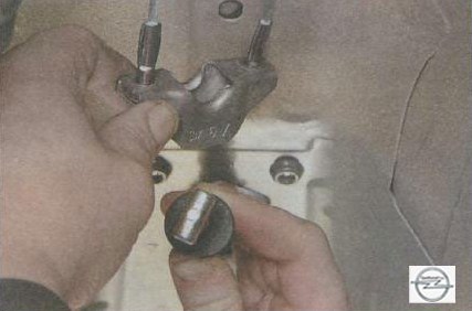
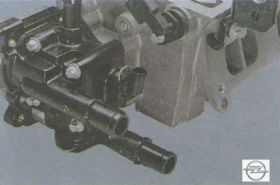
Thermostat module , in a plastic case of which there is a coolant temperature sensor and (depending on the configuration) a valve for regulating the supply of fluid to the heater radiator can be installed, is installed on the rear end of the cylinder head (for clarity, it is shown on the removed cylinder head). A water distribution pipe 1 (see Fig. 1) and hoses 3 and 5 of the heater radiator are connected to the module.
Electric fan 1 (see Fig. 2) with a plastic seven-blade asymmetric impeller provides air purge of the radiator at low speeds of the Opel Astra, mainly in urban areas or on mountain roads, when the oncoming air flow is insufficient to cool the radiator.
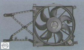
To increase the efficiency of work, the fan is installed in the casing and attached to it at three points through rubber cushions. The casing, in turn, is attached to the radiator 2 at four points.
The electric fan is controlled by the engine control unit, which receives information about the coolant temperature from the coolant temperature sensor located in the thermostat housing.
On Opel vehicles with air conditioning, as an option, an additional electric fan 7 can be installed, designed to blow the heat exchanger 5 of the air conditioner. In this case, to turn on the electric fans, the engine control unit additionally uses information from the air conditioner high and low pressure sensors.
The interior heater radiator is connected to the cooling system with the help of hoses 3 and 5 (see Fig. 1).
- Source http://www.automnl.com/model/opel_astra_h2/253/