![1 generation [2004 - 2013]](/uploads/Lada_Kalina_2004-2013_._.jpg)
On Lada Kalina cars, an ECM (electronic engine control system) (fuel injection system) with an electronic control unit (controller) of the Bosch M 7.9.7 type is installed.
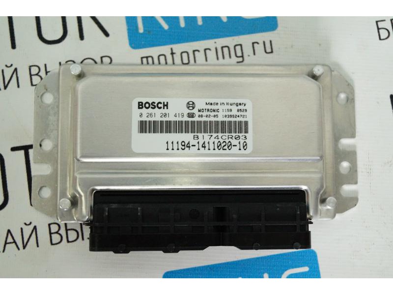
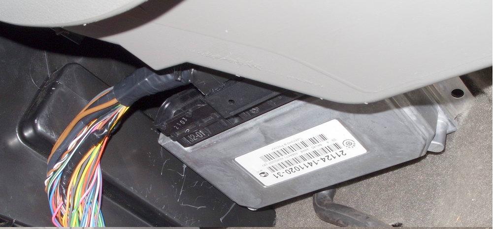
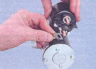
Bosch M 7.9.7 controller - 11194-1411020-10
Electronic control unit VAZ Lada Kalina 1118
On Lada Kalina cars, the controller is the central device of the engine management system. It receives information from sensors and controls the actuators, ensuring optimal engine operation at a given level of vehicle performance.
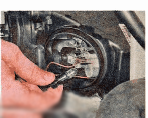
The actuators for the ECU are the idle speed controller, ignition coils, fuel injectors, oxygen sensor heater, canister purge valves, main relay and other components. During operation, the ECU communicates with the immobilizer (provided that this mode is enabled) via a digital interface.
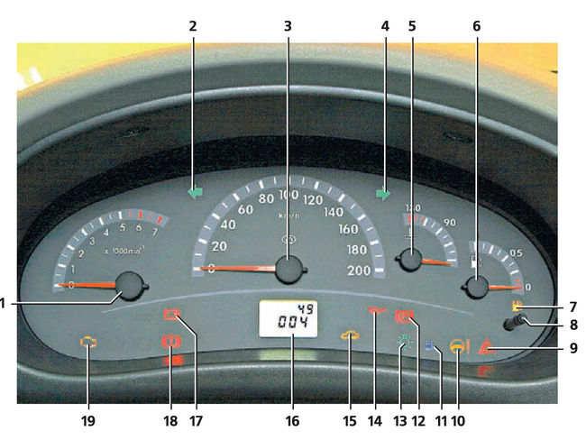
In addition, the electronic control unit performs diagnostics of the VAZ Lada Kalina 1118 engine control system : in the event of a malfunction, the indicator located on the instrument panel turns on, and at the same time error codes are recorded and stored in the computer’s own non-volatile memory, indicating the nature of the malfunction and helping the mechanic to carry out repairs .
Reading is performed using special equipment: a personal computer, cable, etc. through the diagnostic K-line. You can also get by with an on-board computer that has the functions of reading ECM errors.
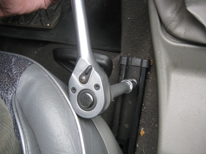
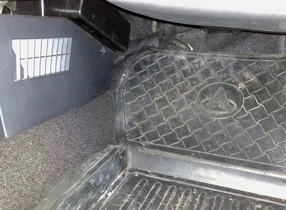
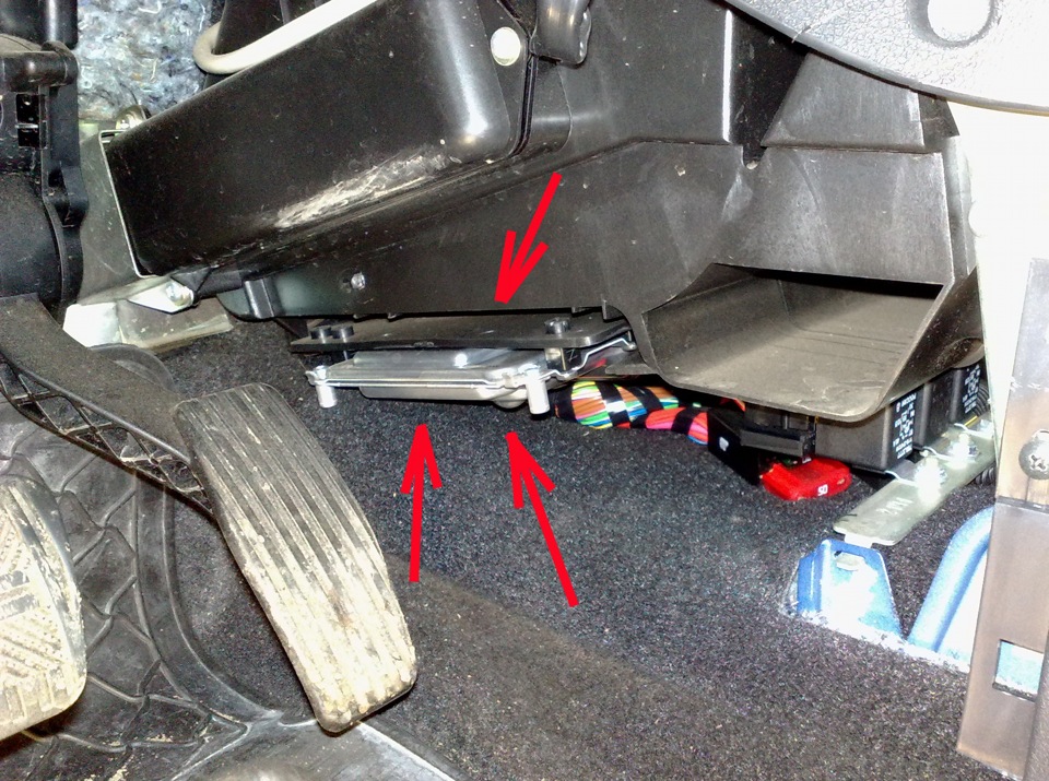
On VAZ-1118 Lada Kalina cars, the ECU controller (electronic control unit) is located at the very bottom of the console between the floor and the heating radiator. Access to it is carried out from the side of the passenger's feet.
Note:
The controller is a complex electronic device that should only be repaired at the factory. During operation and maintenance of the vehicle, disassembly of the controller is prohibited. Unauthorized modification of the controller software can lead to a deterioration in the performance of the engine and even to its breakdown. In this case, the warranty obligations of the vehicle manufacturer for maintenance and repair of the engine and control system are lost.
The sequential multiport fuel injection system (with phased injection) works in conjunction with an exhaust gas converter, a fuel vapor recovery system and ensures compliance with Euro-2 and Euro-3 standards while maintaining high driving performance and low fuel consumption.
The wiring diagrams of the Lada Kalina VAZ 1118 fuel injection system for Euro-2 and Euro-3 toxicity standards are shown below.
Wiring diagram 1 (Euro 2)
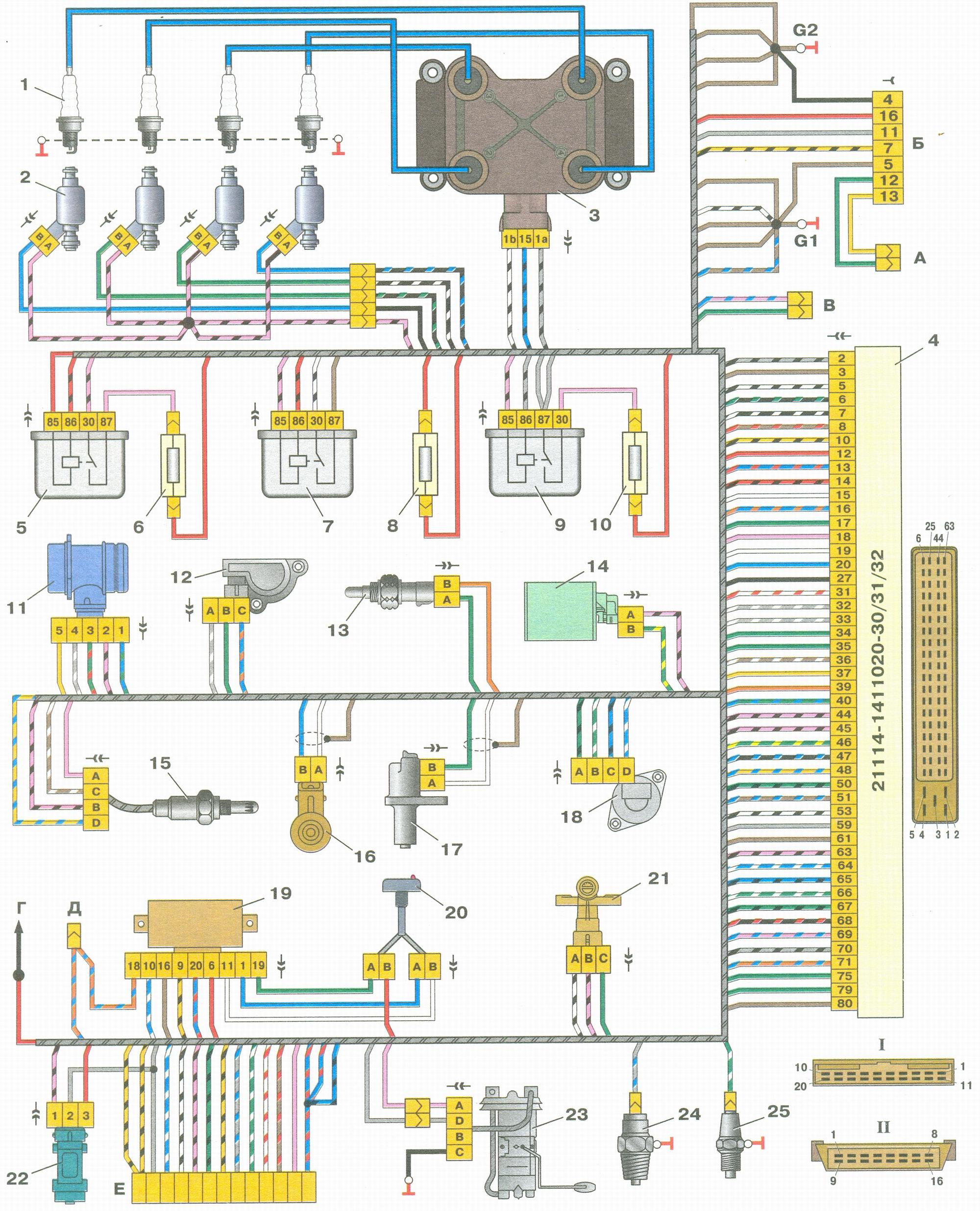
Connections of the engine management system for Euro-2 toxicity standards Lada Kalina (VAZ 1118):
1 - spark plugs;
2 - nozzles;
3 - ignition coil;
4 - controller;
5 - main relay;
6 - main relay circuit fuse;
7 - electric fan relay;
8 - electric fan circuit fuse;
9 - relay of the electric fuel pump;
10 - fuse for the electric fuel pump circuit;
11 - mass air flow sensor;
12 - throttle position sensor;
13 - coolant temperature sensor;
14 - solenoid valve for adsorber purge;
15 - oxygen concentration sensor;
16 - knock sensor;
17 - crankshaft position sensor;
18 - idle speed regulator;
19 - immobilizer control unit;
20 - immobilizer status indicator;
21 - phase sensor;
22 - speed sensor;
23 - fuel pump module;
24 - oil pressure warning lamp sensor;
25 - coolant temperature indicator sensor;
And - the socket attached to a plait of antiblocking system of brakes (ABS);
B - diagnostic connector;
B - connector attached to the wiring harness of the air conditioner;
G - to the "+" terminal of the battery;
D - to the side door wiring harness connector;
E - connector attached to the instrument panel wiring harness;
G1, G2 - grounding points;
I - the order of the conditional numbering of the contacts in the wire connector of the immobilizer control unit;
II - the order of the conditional numbering of the contacts in the diagnostic connector.
Wiring diagram 2 (Euro 3)
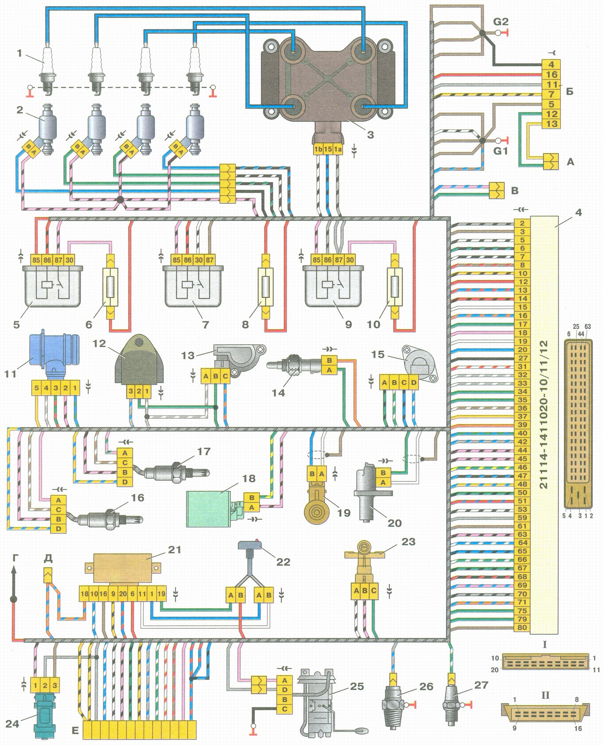
Connections of the engine management system for Euro-3 toxicity standards Lada Kalina (VAZ 1118):
1 - spark plugs;
2 - nozzles;
3 - ignition coil;
4 - controller;
5 - main relay;
6 - main relay circuit fuse;
7 - electric fan relay;
8 - electric fan circuit fuse;
9 - relay of the electric fuel pump;
10 - fuse for the electric fuel pump circuit;
11 - mass air flow sensor;
12 - rough road sensor;
13 - throttle position sensor;
14 - coolant temperature sensor;
15 - idle speed regulator;
16 - control oxygen concentration sensor;
17 - diagnostic oxygen concentration sensor;
18 - solenoid valve for adsorber purge;
19 - knock sensor;
20 - crankshaft position sensor;
21 - immobilizer control unit;
22 - immobilizer status indicator;
23 - phase sensor;
24 - speed sensor;
25 - fuel pump module;
26 - oil pressure warning lamp sensor;
27 - coolant temperature indicator sensor;
And - the socket attached to a plait of antiblocking system of brakes (ABS);
B - diagnostic connector;
B - connector attached to the wiring harness of the air conditioner;
G - to the "+" terminal of the battery;
D - to the side door wiring harness connector;
E - connector attached to the instrument panel wiring harness;
G1, G2 - grounding points;
I - the order of the conditional numbering of the contacts in the wire connector of the immobilizer control unit;
II - the order of the conditional numbering of the contacts in the diagnostic connector.
Source: carpedia.club