![5J [restyling] [2010 - 2015]](/uploads/Skoda_Fabia_5J_2010_-_2015_.jpg)
![6Y [restyling] [2002 - 2007]](/uploads/0427389.jpg)

Tools:
- torque wrench
Parts and consumables:
- Nuts of fastening of a pedal knot
Disconnecting the brake pedal from the pusher of the vacuum booster
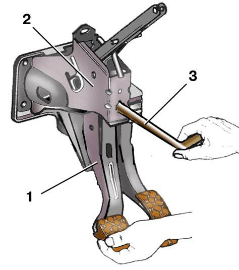
1 - brake pedal;
2 - bracket;
3 - metal rod.
Pedal assembly
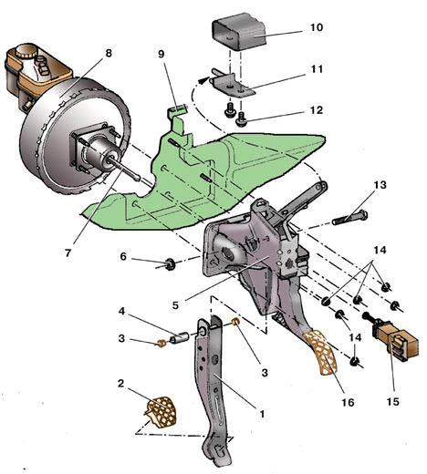
1 - brake pedal;
2 - overlay;
3 - plastic sleeve;
4 - axle bushing;
5 - bracket;
6, 14 - nuts;
7 - pusher of the vacuum booster;
8 - vacuum amplifier;
9 - bulkhead shield;
10 - instrument panel bracket;
11 - amplifier support;
12 - bolt;
13 - pedal axis;
15 - brake signal switch;
16 - accelerator pedal.
Mounting the pedal assembly
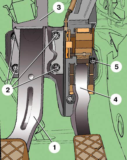
1 - brake pedal;
2, 5 - nuts;
3 - bracket;
4 - accelerator pedal.
Connecting the brake pedal to the pusher of the vacuum booster
1 - pusher of the vacuum booster;
2 - bracket;
3 - brake pedal.
Warning:
Make sure that additional floor mats do not reduce brake pedal travel.
Removing the pedal assembly
1. Disconnect a wire from the plug "-" of the storage battery.
2. Remove a ware box from outside the driver.
3. Turn away a bolt of fastening and remove an air duct of an obduv of the legs of the driver. On models equipped with the Comfort system, remove the central control unit.
4. Remove the brake signal switch 15 (see. Fig. Pedal assembly).
5. Disconnect the shoe 2 from the accelerator pedal position sensor 3.
6. Disconnect the brake pedal 3 (see Fig. Connecting the brake pedal to the pusher of the vacuum booster) from the pusher of the vacuum booster 1.
7. To do this, press the pedal 1 all the way (see Fig. Disconnecting the brake pedal from the pusher of the vacuum booster) of the brake and insert a suitable metal rod 3 into the holes for the brake signal switch of the bracket 2 and the pedal.
8. Pull the pedal 1 towards you, pushing the ball tip of the pusher 7 out of the retainer into the pedals using a rod (see Fig. Pedal assembly).
9. Turn away two plastic nuts 1 fastenings of a casing of a cardan shaft of a steering column and remove a casing 2.
10. Unscrew six nuts 2 and 5 fastening the bracket of the pedal assembly (see Fig. Mounting the pedal assembly - the upper nut is not visible in this figure, all nuts are shown in Fig. Pedal assembly, pos. 14).
11. Remove the pedal assembly from the studs.
Installation of the pedal assembly
1. Install the pedal assembly in reverse order.
2. Replace the pedal assembly mounting nuts with new ones.
3. Fix in a pedal 3 brakes (fig. Connection of a pedal of a brake to a pusher of the vacuum amplifier see) a spherical tip of a pusher 1 of the vacuum amplifier.
The moment of an inhaling of nuts of fastening of an arm of a pedal knot - 28 Н·м.
The article is missing:
- Tool photo
- Photo of parts and consumables
- High-quality repair photos
Source: http://www.navigator.mn/skoda-fabia.html