![4 generation [2001 - 2005]](/uploads/Volkswagen_Polo_2005_-_2009_.jpg)
![5 generation [2009 - 2015]](/uploads/Volkswagen_Polo_2009-2015_.jpg)

-
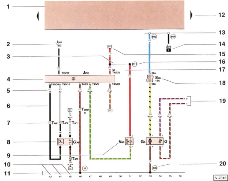
1 - relay board
Indicated by a gray field. Shows connections with a positive pole.
2 - designation of the part to which the wire is directed
J3B2 - Anti-theft control unit, T6/2 - Plug connector, 6-pin, pin 2.
3 - internal connection (thin line)
This connection is not made by wire.
4 - graphic designation of an electrical circuit element
The shown open side of the graphic designation of an electrical circuit element indicates the continuation of the element on another electrical circuit.
5 - cross section in mm^2 and wire color
0.5 = 0.5 mm?, sw = black. For wire color abbreviations, see the Electrical Schematic Familiarity chapter.
6 - electrical circuit made by wire
All switches and contacts are shown in mechanical rest.
7 - plug connector
T4 = male connector, 4-pin; 4 = pin 4.
8 - graphic designation of an electrical circuit element
G39 - heated oxygen sensor.
9 - symbolic designation of an electrical circuit element
N80 - solenoid valve 1. In the explanations under the electrical diagram, the full name of the electrical circuit element is given.
10 - electric circuit number
11 - electric mass of the car
12 - arrow
Indicates the continuation of the wiring diagram on the adjacent page.
13 - pin on the relay board
The white circle indicates that this is a plug connection.
14 - relay location number
Indicates the position number of the relay on the board.
15 - indicator of the further direction of the wire
The number in the square indicates to which current circuit this wire goes next; here - to the electrical circuit 114.
16 - connection in the wiring harness
17 - connector location designation
Here: terminal 30, 45-pin connector, pin 21.
18 - fuse designation
S28 = fuse no. 28.15 A.
19 - indication of the continuation of the wire in the adjacent electrical circuit
The letter indicates which wire in the following diagram is the continuation of that wire.
20 - The circled number indicates the ground or ground connection in the wiring harness.
The explanations below the diagram indicate the ground connections in the vehicle.
-
Source http://automanualsrepair.ru/volkswagen/volkswagen91692.htm