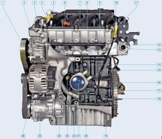
![1 generation [2010 - 2015]](/uploads/Renault_Duster_2010-2015_.jpg)

In accordance with the maintenance regulations, the timing belt (timing) is replaced every 60 thousand
kilometers of the car or after 4 years (whichever comes first), regardless of its condition.
Failure of the belt (broken or sheared teeth) will lead to sticking of the valves into the pistons due to a mismatch in the angles of rotation of the crankshaft and camshafts and, as a result, to expensive engine repairs.
Therefore, we recommend checking the condition of the belt every time the car is serviced.
We perform work on a viewing ditch or overpass.
The surface of the toothed part of the belt must not have folds, cracks, undercutting of the teeth and delamination of the fabric from the rubber.
The reverse side of the belt should not have wear, exposing the cord threads, and signs of burning.
On the end surfaces of the belt there should be no delaminations and fraying.
The belt must also be replaced if traces of oil are found on it.
It should be noted that there are no marks on the engine timing pulleys (1.6 and 2.0) for setting the engine valve timing - at authorized dealer services, when replacing the timing belt, a special tool and fixtures are used to fix the crankshaft and camshafts.
It should also be borne in mind that the manufacturer recommends changing not only the toothed belt, but also its tension and support rollers, as well as the auxiliary drive pulley mounting bolt.
Therefore, we recommend that the timing belt replacement operations be performed at a specialized service that has the necessary equipment and spare parts.
At the same time, an experienced driver with the appropriate skills to repair modern engines will be able to perform the timing belt replacement operations on their own.
To assess the condition and replace the timing belt, remove the right support of the power unit and the right mudguard of the engine compartment.
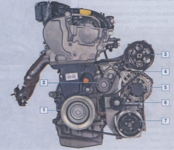
On the engine 1.6
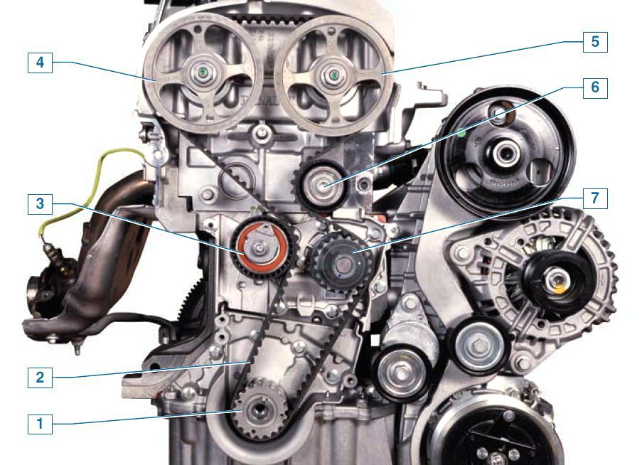
Timing mechanism drive: 1 - crankshaft toothed pulley; 2 - timing belt; 3 - tension roller; 4 – a gear pulley of a camshaft of a drive of final valves; 5 - a gear pulley of a camshaft of a drive of inlet valves; 6 - support roller; 7 – a gear pulley of the pump of a cooling liquid
For clarity, the operation is shown on a dismantled engine.
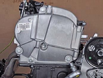
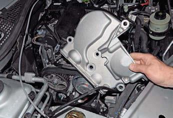
With the “13” head, we unscrew the three bolts and two nuts securing the upper timing cover ...
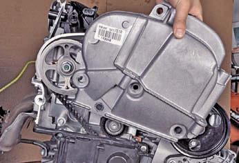
... and remove the cover.
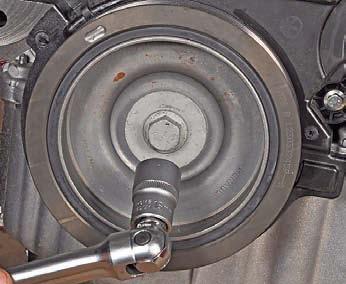
With the “18” head, we turn the crankshaft clockwise for the bolt securing the auxiliary drive pulley and visually assess the condition of the timing belt, as described above.
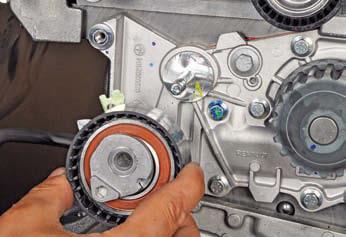
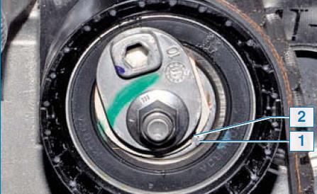
You can estimate the belt tension by the location of the belt tension roller pointers.
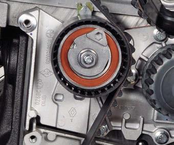
With normal belt tension, the movable pointer should coincide with the notch of the fixed pointer of the tension roller (for clarity, shown with the lower timing cover removed).
If the movable pointer is slightly offset relative to the fixed counterclockwise, then the belt tension is not enough and the belt can be tightened.
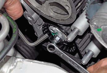
For this…

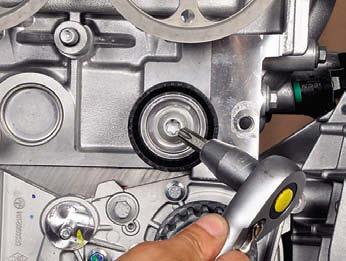
... we loosen the tightening of the tension roller fastening nut with the “13” wrench and turn the roller clockwise with the “6” hexagon (pulling the belt) until the pointers are aligned.
Holding the roller in this position, tighten the nut of its fastening.
Having turned the crankshaft two turns clockwise for the bolt securing the auxiliary drive pulley, we again check the belt tension and, if necessary, repeat the adjustment.
Install the dismantled parts in reverse order.
To replace the timing belt, remove the accessory drive belt and the top timing cover (see above).
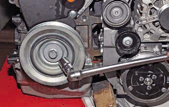
Before loosening the bolt securing the accessory drive pulley, it is necessary to block the crankshaft from turning.
To do this, the assistant must include the highest gear in the gearbox (5th or 6th), press the brake pedal and apply the parking brake.
Using the “18” head, we unscrew the bolt securing the auxiliary drive pulley ...

... and take out the bolt with the washer.
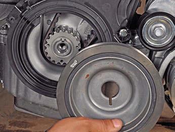
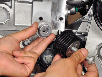
Remove the accessory drive pulley.
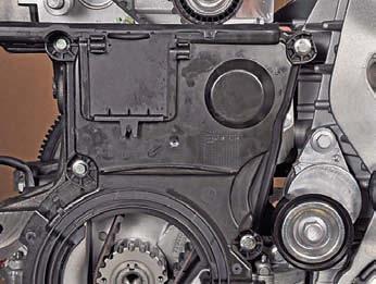
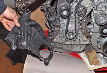
With the “8” head, we unscrew the four bolts securing the lower timing cover ...
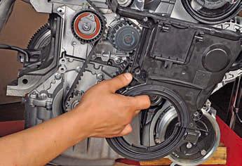
... and remove the cover.
In order not to disturb the valve timing, before removing the timing belt, it is necessary to set the crankshaft and camshafts to the TDC (top dead center) position of the compression stroke of the 1st cylinder.
To rotate the crankshaft, we screw in place the bolt securing the auxiliary drive pulley by installing a spacer (sleeve or set of washers) between the bolt and the end of the shaft.
The crankshaft can also be rotated by rotating the (in place) front right wheel clockwise with the transmission in top gear (5th or 6th).
In order to facilitate turning the shaft, we turn out the spark plugs.
To determine the position of the camshafts, it is necessary to remove two rubber-metal plugs from the holes in the left end of the cylinder head.
We remove the air intake with the air path resonator.
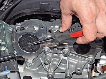
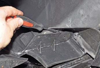
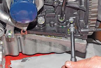
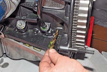
In the center of the plug (rubber array), we pierce a hole with a screwdriver and, acting with a screwdriver as a lever ...
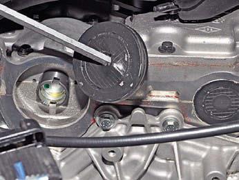
... remove the plug from the hole in the cylinder head.
Remove the other plug in the same way.
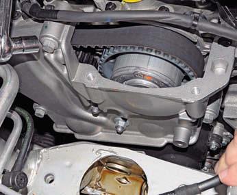
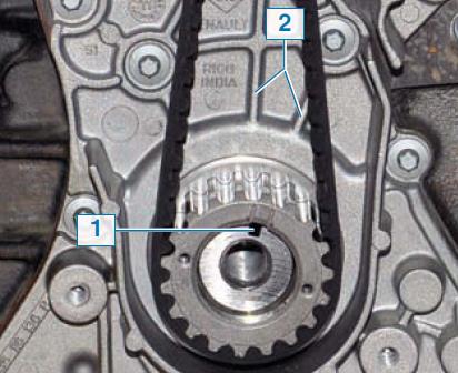
Turn the crankshaft clockwise until...

... until the grooves on the ends of the camshafts take a horizontal position (they are parallel to the plane of the connector of the cover and the cylinder head) and are shifted down relative to the axes of the camshafts.
To fix the camshafts when replacing the belt, a simple tool can be made from a metal plate 5 mm thick (see
sketch).
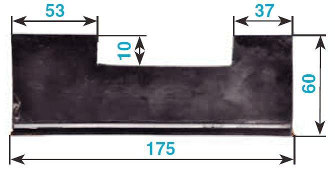
Device for fixing camshafts.
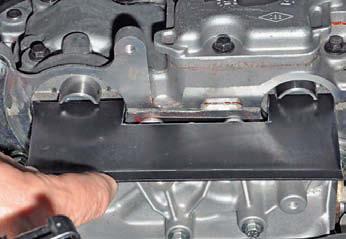
We install the device in the grooves of the shafts.
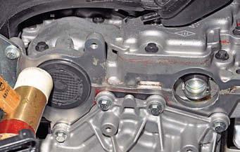
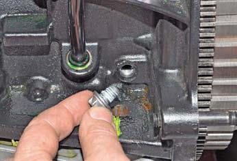
To check that the crankshaft is in the TDC position of the pistons of the 1st and 4th cylinders, a threaded hole is provided on the front wall of the cylinder block (under the starter), plugged with a plug.
Using the E-14 head, unscrew the plug (as shown on the 2.0 engine).
A special locating pin (with a threaded length of 75 mm) must be screwed into the hole.
When the crankshaft is in the TDC position of the pistons of the 1st and 4th cylinders, the finger should rest against the milled platform on the cheek of the crankshaft and block the shaft when trying to turn it clockwise.
An M10 bolt can be used as a mounting pin.

We screw two adjusting nuts onto the bolt and lock them so that the length of the threaded part of the bolt is 75 mm.
We screw the assembled fixture (installation pin) into the threaded hole of the cylinder block.
When the crankshaft is in the TDC position of the pistons of the 1st and 4th cylinders ...
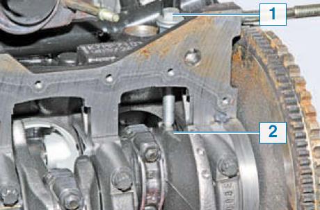
... the mounting pin 1 must be screwed into the hole to the end of the thread and rest against the milled platform 2 on the crankshaft web (shown with the oil pan removed).
In this case, the crankshaft cannot be turned clockwise.
If, when screwing in the adjusting pin, it rests, and the end of the adjusting nut on the pin does not come into contact with the end face of the boss of the hole in the cylinder block (there will be a gap between the nut and the boss), then you need to turn the crankshaft counterclockwise a little (by removing the device from the grooves of the camshafts) arrows.
Then you need to screw the mounting pin into the hole in the cylinder block to the end (until the ends of the pin nut and the boss of the hole in the block touch) and turn the crankshaft clockwise until the shaft cheek pad stops against the pin.
We install the device for fixing the camshafts, if it was removed.
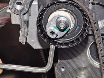
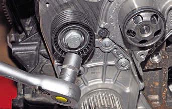
Having loosened the tightening of the tension roller fastening nut with the “13” wrench ...

... turn the roller counterclockwise, reducing the tension of the timing belt ...
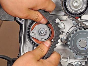
... remove the belt from the tension roller ...
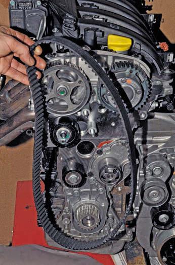
... and then from the coolant pump pulleys, crankshaft and camshafts.

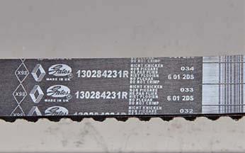
Timing belt marking (number of teeth -131, width 25.4 mm).
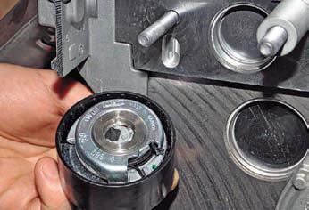
When replacing the belt, the tension and support rollers must also be replaced.
We unscrew the nut securing the tension roller ...
... and remove it from the stud of the coolant pump housing.
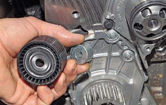
With a Torx T-50 wrench, unscrew the screw securing the support roller.
Remove the support roller and its bushing.
Install the new support roller in reverse order.
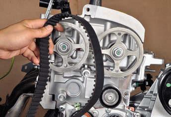
When installing a new timing belt (on which arrows are applied), we orient it so that the arrows coincide with the direction of movement of the belt (clockwise).
We install the belt on the gear pulleys of the crankshaft, coolant pump and camshaft pulleys.
Then, at the same time, we put the belt on a new tension roller and install the roller on the stud of the coolant pump housing.
When installing the tension roller ...
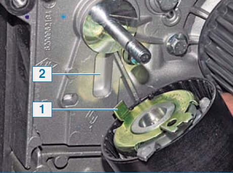
... insert the bent end 1 of the roller bracket into the recess 2 of the coolant pump housing.
We adjust the tension of the timing belt (see
above).
We unscrew the adjusting pin from the hole in the cylinder block and remove the device for fixing the camshafts.
We turn the crankshaft two turns clockwise until the grooves on the ends of the camshafts take the desired position (see
above).
We check the valve timing and belt tension.
If necessary, repeat the steps to install the timing belt.
We wrap the cork in the hole in the cylinder block.
With light blows of a hammer with a plastic striker, we press new plugs into the holes of the cylinder head.
Further assembly of the engine is carried out in the reverse order.
We replace the auxiliary drive pulley bolt with a new one and tighten it to the prescribed torque.
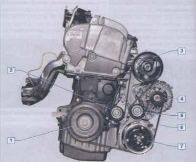
On 2.0 engine

Engine timing gear drive 2.0: 1 - crankshaft toothed pulley; 2 - timing belt; 3 – a basic roller of a belt; 4 – a tension roller of a belt; 5 – a gear pulley of a camshaft of final valves; 6 - the actuator of the system for changing the valve timing; 7 – a pulley of the pump of a cooling liquid
With the “13” head, we unscrew the three bolts and two nuts securing the upper timing cover ...
... and remove the cover.
With the “18” head, we turn the crankshaft clockwise for the bolt securing the auxiliary drive pulley and visually assess the condition of the timing belt (see above).
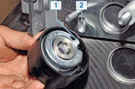
You can estimate the belt tension by the location of the belt tension roller pointers.
With normal belt tension, the movable pointer 1 should coincide with the notch of the fixed pointer 2 of the tension roller (for clarity, shown with the lower timing cover removed).
If the movable pointer is slightly offset relative to the fixed counterclockwise, then the belt tension is not enough and the belt can be tightened.
For this…
... with a “10” ring wrench, loosen the tightening nut of the tension roller and with a “6” hexagon, turn the roller clockwise (pulling the belt) until the pointers are aligned.
Holding the roller in this position, tighten the nut of its fastening.
Having turned the crankshaft two turns clockwise for the bolt securing the auxiliary drive pulley, we again check the belt tension and, if necessary, repeat the adjustment.
Install the dismantled parts in reverse order.
To replace the timing belt, remove the accessory drive belt and the top timing cover (see above).
Before loosening the bolt securing the accessory drive pulley, it is necessary to block the crankshaft from turning.
To do this, the assistant must include the highest gear in the manual transmission, press the brake pedal and apply the parking brake.
If at the same time it is not possible to unscrew the bolt securing the pulley due to turning the crankshaft, then the shaft must be locked.
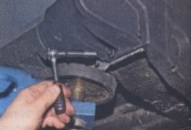
To do this, we unscrew the bolt and take out the piston for fastening the plastic holder of the wiring harnesses to the clutch housing and remove the holder with the wiring harnesses from the clutch housing.
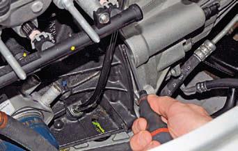
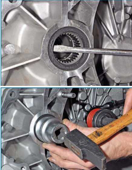
We insert a slotted screwdriver through the window in the clutch housing between the teeth of the flywheel crown (for clarity, it is shown with the cooling system hoses removed).
For clarity, we show further operations on a dismantled engine.
Using the “18” head, we unscrew the bolt securing the auxiliary drive pulley and remove the bolt with the washer.
Remove the accessory drive pulley.

With the “8” head, we unscrew the five bolts securing the lower timing cover ...
... and remove the cover.
In order not to disturb the valve timing, before removing the timing belt, it is necessary to set the crankshaft and camshafts to the TDC (top dead center) position of the compression stroke of the 1st cylinder.
To rotate the crankshaft, we screw in place the bolt securing the auxiliary drive pulley by installing a spacer (sleeve or set of washers) between the bolt and the end of the shaft.
The crankshaft can also be rotated by turning the (in place) front right wheel clockwise with the manual transmission in top gear (5th or 6th).
In order to facilitate turning the shaft, we turn out the spark plugs.
We remove the plugs of the camshafts and turn the crankshaft clockwise until the grooves on the ends of the camshafts take a horizontal position (located parallel to the plane of the connector of the cover and the cylinder head) and are shifted down relative to the axes of the camshafts (as shown on engine 1 ,6 - see above).
We turn the E-14 head out of the hole in the cylinder block ...
... screw plug.
We insert an adjusting pin into the hole of the cylinder block - a rod with a diameter of 8 mm and a length of at least 70 mm (you can use a drill shank with a diameter of 8 mm).
When the crankshaft is in the TDC position of the pistons of the 1st and 4th cylinders, the finger should enter the rectangular groove on the cheek of the crankshaft and block the shaft when trying to turn it in one direction or another.
With the correct position of the crankshaft ...
... the keyway 1 on its toe should be located between the two ribs 2 of the cylinder block cover.
To set the valve timing when assembling the engine (after its repair), it is convenient to control the position of the crankshaft at TDC of the pistons of the 1st and 4th cylinders ...

... by coincidence of the cavity 1 of the setting disk (for the crankshaft position sensor) on the flywheel with the tide 2 on the cylinder block (3 - the hole for the bolt of the upper front mounting of the gearbox).
We install a device for fixing them in the grooves of the camshafts (as shown on the 1.6 engine - see above).
Having loosened the tightening nut of the tension roller with the “10” wrench ...
... with a “6” hexagon, turn the roller counterclockwise, loosening the belt tension).
Remove the timing belt from the gear pulleys of the camshafts and crankshafts.
Timing belt marking (number of teeth -126, width 25.4 mm).
When replacing the belt, the tension and support rollers must also be replaced.
Loosen the nut...
... remove the tension roller from the cylinder head stud.
Using the “16” head, unscrew the bolt securing the support roller to the cylinder block.
Remove the support roller and its mounting sleeve.
We install a new support roller in the reverse order and tighten the bolt of its fastening to the prescribed torque.
When installing the tension roller ...
... insert the bent end 1 of its bracket into the recess 2 of the cylinder head and bait the roller nut.
When installing a new timing belt (on which arrows are applied), we orient it so that the arrows coincide with the direction of movement of the belt (clockwise).
We install the belt on the toothed pulleys of the crankshaft and camshafts.
We start the front branch of the belt under the coolant pump pulley, and the rear branch - under the tension and support rollers.
We adjust the tension of the timing belt (see above).
We take out the adjusting pin from the hole in the cylinder block and remove the device for fixing the camshafts.
We turn the crankshaft two turns clockwise until the grooves on the ends of the camshafts take the desired position (see above).
We check the valve timing and belt tension and, if necessary, repeat the adjustments.
We install the screw plug in place and press in new plugs for the camshafts (as shown on the 1.6 engine - see above).
Further assembly of the engine is carried out in the reverse order.
We replace the auxiliary drive pulley bolt with a new one and tighten it to the prescribed torque.
Source: http://www.renault-duster.dv13.ru/dvigatel/proverka-sostoyaniya-i-zamena-remnya-privoda-gazoraspredelitelnogo-mexanizma/