![E140/E150 [2006 - 2010]](/uploads/Toyota_Corolla_E140_2006_-_2010_.jpg)

Most vehicle electrical power circuits are protected by fuses. Powerful current consumers are connected via relays. Fuses and relays are installed in mounting blocks located in the passenger compartment and in the engine compartment.
Most of the fuses are installed in the passenger compartment relay and fuse mounting block (Figure 2), located on the lower left side of the instrument panel (the electronic body control unit is installed in the same block).
 Picture 1.
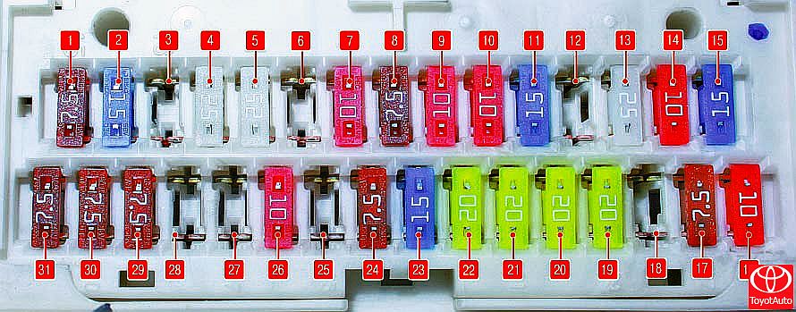
Fuse numbers in the mounting block located in the passenger compartment
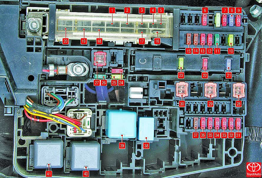 Figure 2.
Designation of fuses, fuses and relays in the mounting block located in the engine compartment
The purpose of the fuses and relays (their numbers are shown in and Figure 2) is indicated in Table 1.
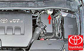
In addition, fuses, relays and fusible links are located in a mounting block installed in the engine compartment on the left side in the direction of travel (Figure 2). Table 1 shows the purpose of these fuses, fuses, and relays, but some of the circuits shown in the table may not be available on a particular vehicle model.
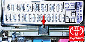 Figure 3
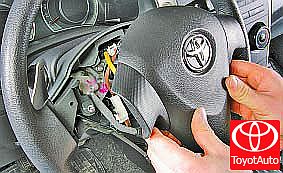
1. To gain access to the fuses of the mounting block located in the passenger compartment, press the latch ...
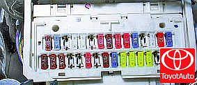 Figure 4
2. ... and remove the cover of the mounting block. The fuse location diagram is printed on the front side of the cover.
3. Before replacing a blown fuse, find out the cause of the blown fuse and fix it. When troubleshooting, look at the circuits listed in Table 1 (see “Onboard Electrical Troubleshooting”) that this fuse protects.
WARNING
Do not replace fuses with jumpers or fuses of a different amperage, or homemade jumpers, as this may damage electrical appliances and even cause a fire.
4. Remove the replacement fuse with tweezers.
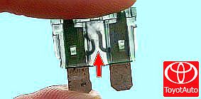 Figure 5
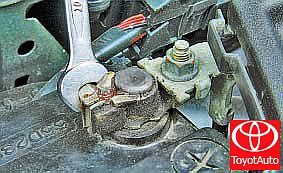
5. This is how a blown fuse looks like (the jumper shown by the arrow inside the holder has blown and opened). To replace a fuse, use a spare fuse of the same rating (and color).
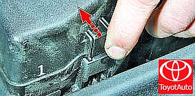 Figure 6
6. To access the fuses and relays of the mounting block located in the engine compartment, press the latch ...
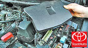 Figure 7
7. ... and remove the cover.
NOTE
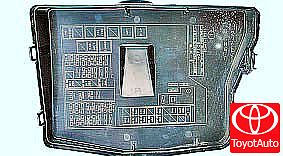 Figure 8
On the inside of the cover there is a diagram of the location of the relays and fuses.
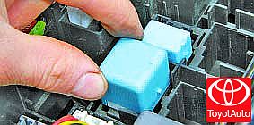 Figure 9
8. If necessary, remove the relay or fuse by rocking it slightly from side to side.
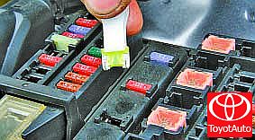 Figure 10
9. Use special tweezers to replace fuses.
10. Install the parts in the reverse order of removal.
Table 1. Purpose of fuses, fuses and relays installed in the mounting block in the engine compartment
| Fuse number (amperage) | Fuse color | Protected circuit |
| 1 (30 A) | - | headlight washer |
| 2 (45 A) | - | Cooling fan |
| 3 (30 A) | - | ABS and VSC systems |
| 4 (50A) | - | Battery Charging System |
| 5 (50 A) | - | ABS and VSC systems |
| 6 (10 A) | Red | Robotic gearbox, air conditioning system, Smart Entry system |
| 7 (10 A) | Red | Instrumentation, body electrical control module, VSC system, central locking, power windows |
| 8 (15 A) | Blue | Audio system |
| 9 (10 A) | Red | Interior lighting, trunk lighting, Smart Entry system |
| 10(20 A) | Yellow | Steering lock system |
| 11 (30 A) | Green | Engine start system, Smart Entry system, injection system |
| 12 (10 A) | Red | Electronic Throttle Control System |
| 13 (10 A) | Red | Direction indicators and alarms |
| 14 (7.5 A) | Brown | Battery Charging System |
| 15 (7.5 A) | Brown | Body electrical control unit |
| 16 (50A) | - | Headlights |
| 17(50 A) | - | fuel injection system |
| 18(80A) | - | Engine preheating system (for diesel engines) |
| 19(60 A) | - | Electric power steering |
| 20 (120 A) | - | Battery Charging System |
| 21 (15 A) | Blue | Fuel injection system, Smart Entry system |
| 22 (10 A) | Red | Sound signal |
| 23 (20 A) | Yellow | fuel injection system |
| 24 (10 A) | Red | Spare fuse |
| 25 (20 A) | Yellow | Also |
| 26 (30 A) | Green | >> |
| 27 (50 A) | - | Robotic gearbox |
| 28 (30 A) | - | Air conditioning system |
| 29 (30 A) | - | Also |
| 30 (30 A) | - | >> |
| 31 (30 A) | Red | Left headlight (low beam) |
| 32 (50 A) | Red | Right headlight (low beam) |
| 33 (30 A) | Red | Left headlight (high beam) |
| 34 (30 A) | Red | Right headlight (high beam) |
| 35 (40 A) | Red | injection system |
| 36 (40 A) | Red | Also |
| 37 (7.5 A) | Brown | Starting system, Smart Entry system |
| 38 | - | Cooling Fan Relay |
| 39 | - | Headlight Switch Relay |
| 40 | - | Robotic gearbox relay |
| 41 | - | headlight relay |
Source: http://toyotauto.net/corolla/raspolozhenie-predohraniteley-plavkih-vstavok-i-rele-i-ih-zamena.html