![1 generation [2001 - 2005]](/uploads/Hyundai_Matrix_2002-2006_.jpg)

Disassembly of the connecting rod cap
|
ATTENTION Arrange the removed parts (connecting rods, connecting rod caps, connecting rod bearing shells) in order of their cylinder numbers to ensure proper reassembly. |
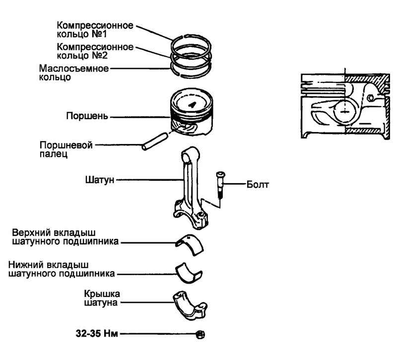
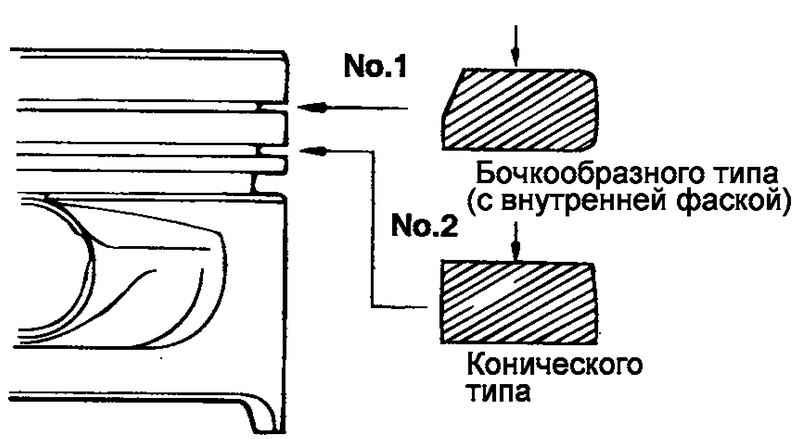
Rice. 2.71. Piston and connecting rod components
Loosen the connecting rod cap bolts, then remove the connecting rod cap and lower connecting rod bearing.
Push the piston and connecting rod assembly out of the cylinder block towards the cylinder head gasket surface.
Disassembly and assembly of the piston and connecting rod assembly (removal and installation of the piston pin)
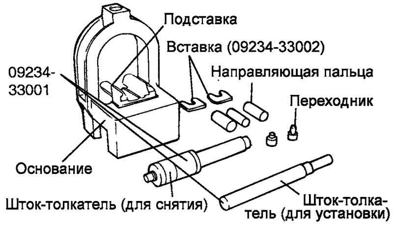
Rice. 2.72. Disassembly of the piston-rod assembly
Using special tools (09234-33001 and 09234-33002), disassemble and assemble the piston and connecting rod assembly (Fig. 2.72).
The piston pin is pressed into the upper head of the connecting rod, and the piston slides over it.
A set of special tools consists of a base with a stand and inserts, guides, adapters, a push rod for removal and a push rod for installation. When removing or installing a piston pin, the piston is held on the base of the tool. Piston guides make it easier to position the piston pin when removing and installing it when the connecting rod rests on the pedestal inserts.
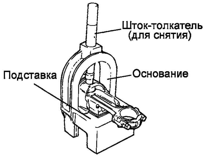
Rice. 2.73. Removing a finger with a press
To remove the piston pin, place the piston on the base and position the connecting rod on the pedestal insert. Insert the pusher rod (for removal) through the arc of the upper part of the base into the piston pin and remove the pin with a press (Fig. 2.73).
When installing a new pin, you must install the appropriate stand insert to support the crank.
Position the top end of the connecting rod inside the piston. On one side of the piston, insert the appropriate guide through the piston and connecting rod, then slightly push the guide back by hand so that it is held by the piston. On the other side of the piston, insert the piston pin and place the piston and connecting rod together on the base of the tool with the pin guide on the bottom.

Rice. 2.74. Connecting rod centering guide
|
NOTE The guide is needed to center the connecting rod relative to the piston bosses. If assembled correctly, the finger guide will be exactly centered on the arc hole on the top of the base and touching the stand insert. If an incorrectly sized guide pin is used, the piston (and connecting rod) and piston pin will not be on the same axis as the base hole ( Fig. 2.74 ). |
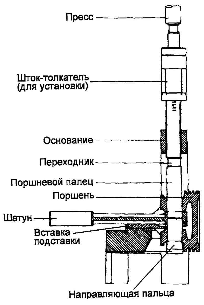
Rice. 2.75. The scheme of pressing the finger into the piston and the upper head of the connecting rod
Insert the push rod (for installation) through the hole in the arc of the upper part of the base until it stops into the adapter on the piston pin and, using a hydraulic press, insert the pin into the piston and the upper head of the connecting rod. Continue pressing until the finger guide falls from the bottom of the base and the push rod rests against the arc of the upper part of the base (Fig. 2.75).
|
ATTENTION Do not exceed the force of 12500 ± 5000 N when pressing the piston pin at the moment when the pusher rod rests against the arc of the upper part of the base. |
Checking the piston and piston pin
Check each piston for scratches, nicks, wear and other defects. Replace piston if defective.
Check each piston ring for breaks, damage or significant wear. Replace defective rings. If a piston needs to be replaced, its piston rings must be replaced at the same time.
Make sure the piston pin fits into the piston bosses. Replace piston and piston pin as a set if defective. At room temperature, under hand pressure, the piston pin should easily enter the piston bore.
Checking piston rings
Measure the gap between the compression ring and the piston groove (Fig. 2.76).
If the measured clearance exceeds the limit, install a new piston ring and re-measure the clearance. If the measured clearance again exceeds the limit value, replace the piston and rings as an assembly. If the measured clearance is less than the limit value, replace only the piston rings.
The clearance values between the piston ring and the piston groove are shown below.
Rated value:
compression ring No. 1 - 0.04–0.085 mm;
compression ring No. 2 - 0.04–0.085 mm.
Maximum allowable value:
compression ring No. 1 - 0.1 mm;
compression ring No. 2 - 0.1 mm.
Rice. 2.77. Checking the clearance in the piston ring lock
For measurement of a backlash in the lock of a piston ring establish a piston ring in an opening of the cylinder (fig. 2.77).
Position the ring at right angles to the generatrix of the cylinder wall, carefully moving it down with the piston.
Measure the gap in the ring lock with a flat feeler gauge (Fig. 2. 78).
If the measured clearance exceeds the limit, replace the piston ring.
Piston ring gap values are shown below.
Rated value:
compression ring No. 1 - 0.20–0.35 mm;
compression ring No. 2 - 0.30–0.45 mm;
oil scraper ring - 0.2–0.7 mm.
Maximum allowable value:
compression rings No. 1 and No. 2 - 1.0 mm;
oil scraper ring - 1.0 mm.
When replacing piston rings without boring the cylinders to the repair size, check the gap in the ring lock at a point located at the bottom of the cylinder (the zone of least wear).
Rice. 2.78. Piston ring gap measurement
|
NOTE The oversize identification mark is located on the top of the piston ring near the ring lock. |
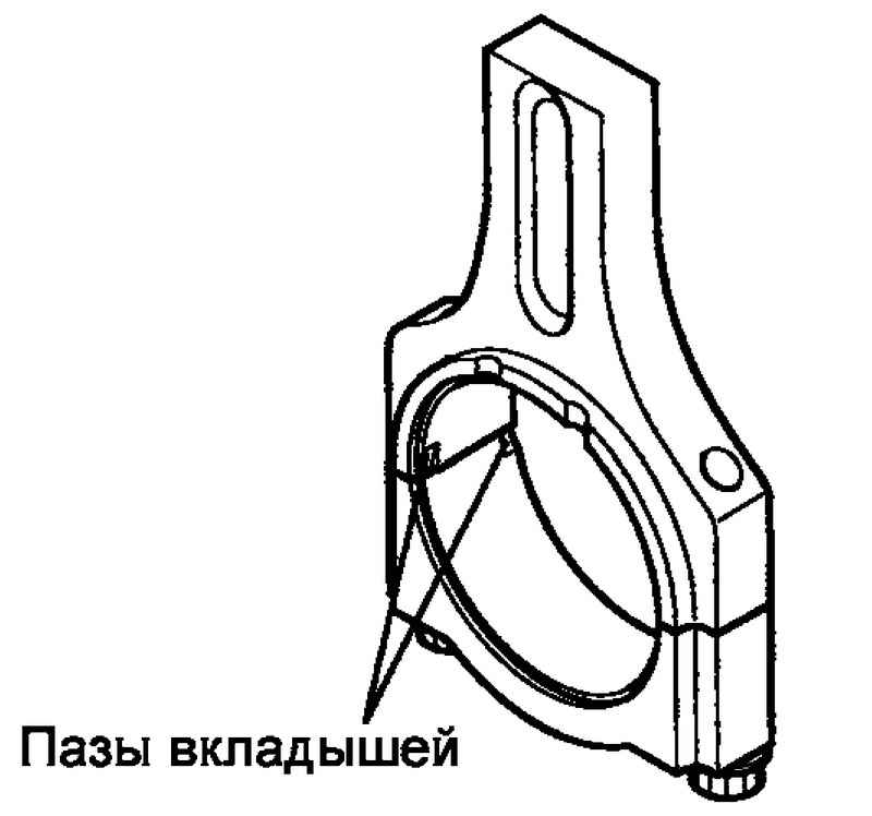
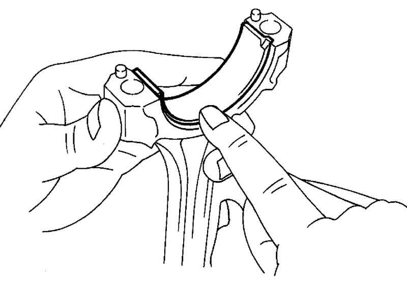
Rice. 2.79. Grooves of loose leaves in a cover of a rod and a rod
When installing the connecting rod cap, make sure that the cylinder number marks (made during disassembly) on the connecting rod and the connecting rod cap match. When installing a new connecting rod, make sure that the fixing grooves of the liners in the connecting rod cap and connecting rod are located on one side (Fig. 2.79).
Replace the connecting rod if there is damage to the end surface of the upper or lower heads. If bending or twisting of the connecting rod is present, or the surface of the piston pin bore in the upper end of the connecting rod is significantly worn, replace the connecting rod.
Assembly
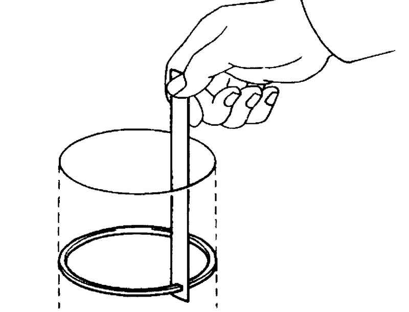
Rice. 2.80. Installing the oil ring expander
Establish an expander of an oil scraper ring (fig. 2.80).
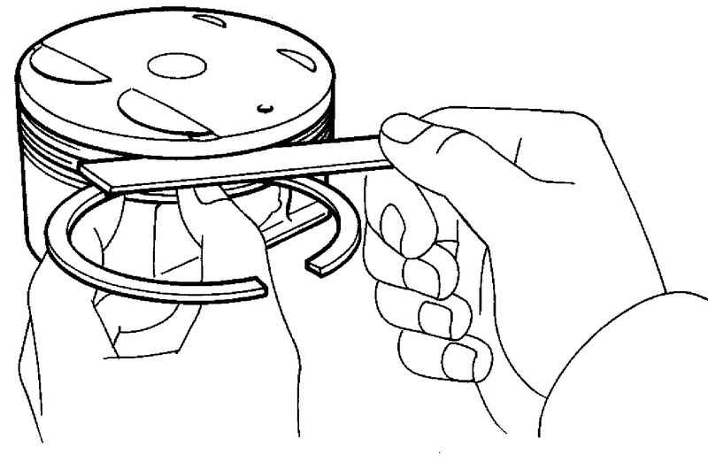
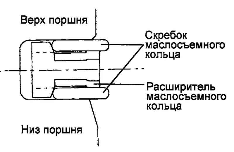
Rice. 2.81. Scheme of installation of the upper scraper of the oil scraper ring
Install the top oil ring scraper. To install the scraper, first place one end of the scraper between the expander and the piston groove, then, holding the end of the scraper, press the scraper with your finger to bring it into the groove, as shown in Figure 2.81.
|
ATTENTION Do not use a piston ring expander when installing oil scraper scrapers. |
Rice. 2.82. Installation of the bottom scraper of an oil scraper ring
Establish the lower scraper of an oil scraper ring according to the previous procedure (fig. 2.82).
Apply engine oil to the piston and piston ring grooves all around.
Using a piston ring expander, install compression ring #2.
Rice. 2.83. Scheme of installation of a compression ring No. 1
Establish a compression ring No. 1 (fig. 2.83).
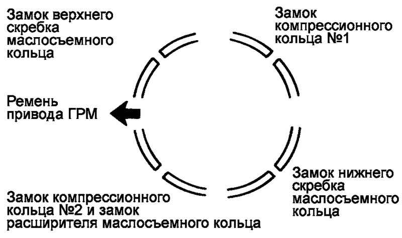
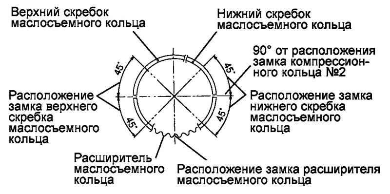
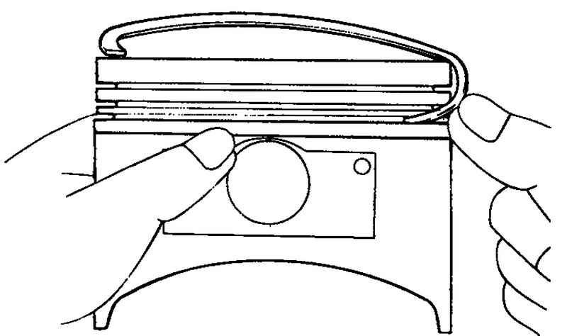
Position the locks of the rings as far apart as possible. Make sure that the lock of any ring is not on the axis of the piston pin or a direction perpendicular to this axis (Fig. 2.84).
Using a tool, secure the piston rings to the piston before installing the piston assembly into the cylinder.
Install the upper main bearing shells to the cylinder block.
Rice. 2.85. Installing the lower main bearing into the connecting rod cap
Establish the bottom loose leaves of radical bearings in covers of rods (fig. 2.85).
When installing, make sure that the “front” mark on the piston and the “front” identification mark on the connecting rod are towards the front of the engine (towards the timing belt).
When installing a new connecting rod, make sure that the retaining grooves of the bushings on the connecting rod and the connecting rod cap are on the same side.
When assembling, the connecting rod cap bolts should be tightened using the angle tightening method as follows:
- Apply oil to the threads of the fastening nuts and the points of contact of the connecting rod of nuts and bolts;
– Tighten bolts of fastening of covers of rods the nominal moment of an inhaling.
The moment of an inhaling of nuts of fastening of covers of rods: 32–35 Nm.
|
ATTENTION Do not reinstall used (removed during disassembly) connecting rod cap bolts. When installing new connecting rod cap bolts, do not tighten them more than three times. |
Check the backlash between the bottom head of the connecting rod and the corresponding web of the crankshaft.
Lateral clearance of the lower head of the connecting rod:
nominal value - 0.1–0.25 mm;
the maximum allowable value is 0.4 mm.
Install the oil pickup.
Install the oil pan.
Install the cylinder head.
Source: http://automn.ru/hyundai-matrix/hyundai-37164-10.m_id-4934.m_id2-4936.html