![B6 [2000 - 2005]](/uploads/Audi_A4_2000-2005_B6_.jpg)
general information
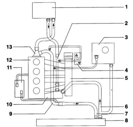
Connection diagram of the cooling system hoses:
- 1 - heater radiator;
- 2 - coolant pipeline lower;
- 3 - expansion tank;
- 4 - oil cooler;
- 5 - inlet pipeline;
- 6 - lower radiator hose;
- 7 - upper radiator hose;
- 8 - radiator;
- 9 - upper coolant pipeline;
- 10 - water pump with thermostat;
- 11 - turbocharger;
- 12 - block and cylinder head;
- 13 - outlet fitting.
On some models, a coolant temperature control system is used, which works according to the characteristic laid down in the control unit. Compared to a conventional cooling system, this system improves the thermodynamic efficiency of the engine and thus optimizes the torque characteristic.
The cooling system, operating according to a given characteristic, consists of a coolant distributor with a thermostat, an electric heating element, as well as springs for mechanically locking the coolant channels.
By means of a heated thermostat, the temperature of the coolant is regulated by the engine control unit according to the characteristics laid down in it. At the same time, the temperature is maintained, which is optimal in terms of engine power output.
For example, when the engine is fully loaded, the expanding element heats up and thus the thermostat opens more. This reduces the temperature of the coolant, which leads to more intensive cooling of the combustion chambers. Cooler combustion chambers lead to earlier ignition and thus more engine torque.
The coolant is directed through the radiator by a constantly running pump. The liquid passes through the radiator from top to bottom and is cooled by the air passing through it. An electrically driven coolant fan is used.
Heater and ventilation
The heater consists of fans and heat exchangers located in the blocks of the front and rear parts of the cabin. The hot coolant flows through the heat exchangers. When the heater mode control knob located on the control panel is moved, the valves open and hot air begins to flow into the vehicle interior. If you turn on the heater fan, air will be forced into the passenger compartment.
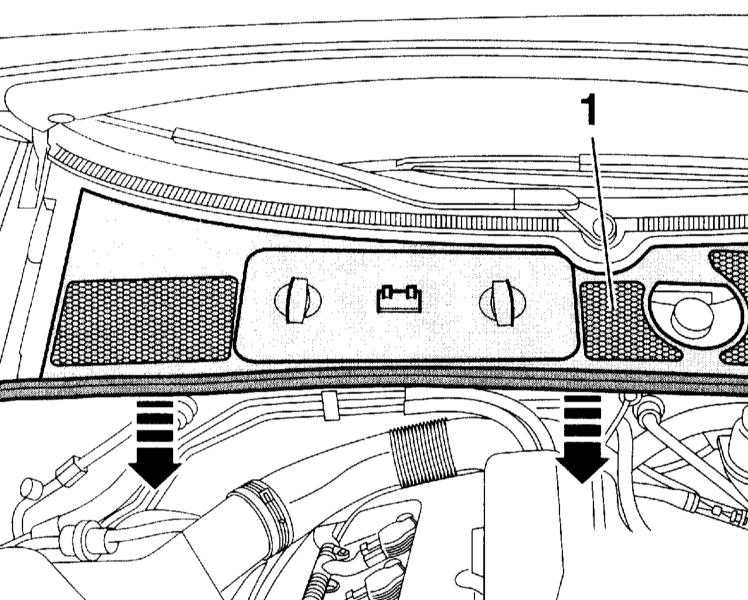
Intake air passes through a filter before entering the passenger compartment. The bulk of the dust particles will settle in the filter. The filter replacement interval must be observed. A filter clogged with dust will restrict the air supply to the passenger compartment, which will lead to stagnation of air inside the passenger compartment.
The distribution of air flows of the ventilation system is carried out with the help of dampers. The mode of air circulation is provided. The dampers are controlled by servomotors.
Source: http://carmanz.com/audi/a4-b6-2000-2004/6510-a420003-1-1.html