![W203/S203/CL203 [2000 - 2004]](/uploads/mercedes-c-klass-w203.jpg)

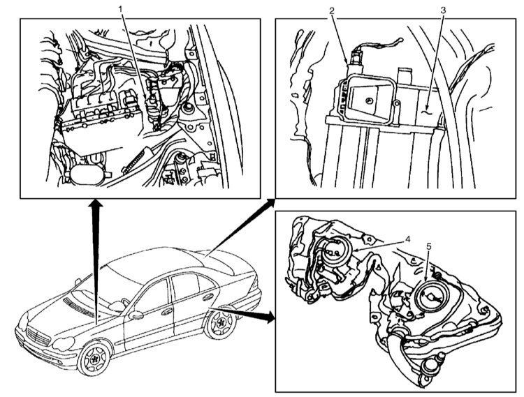
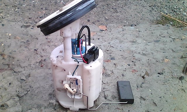
The layout of the components of toxicity reduction systems. Models C240 and C320 :
1 - adsorber purge control valve;
2 - shut-off valve of the coal adsorber;
3 - carbon adsorber;
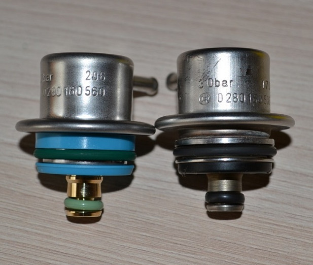
4 - pressure sensor in the fuel tank;
5 - fuel pump.
Canister Purge Control Valve
Carbon adsorber cut-off valve
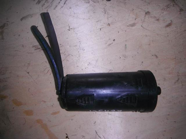
Carbon adsorber
Fuel tank pressure sensor
Fuel pump
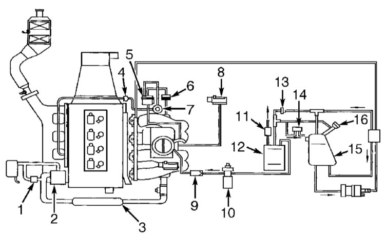
Diagram of connection of vacuum lines of the model with the engine 111 equipped with an air compressor:
1 - actuating device of the recirculation damper;
2 - air compressor;
3 - intercooler (Intercooler);
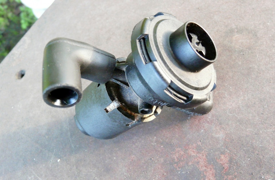
4 - control valve for mixing secondary air;
5 - air pump switch valve;
6 - vacuum control valve;
7 - secondary air cut-off valve;
8 - pressure sensor;
9 - control valve (coal adsorber);
10 - control valve for purge of the coal adsorber;
11 - cut-off valve of the coal adsorber;
12 - carbon adsorber;
13 - ventilation valve;
14 - pressure relief valve (ORVR);
15 - fuel tank;
16 - filler neck of the fuel tank with a connector for the fuel vapor recovery system.
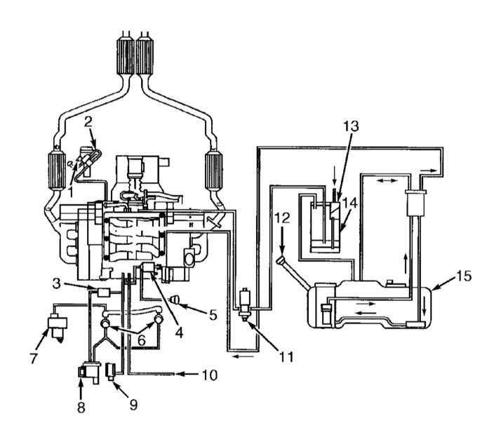
Diagram of connection of vacuum lines of the model with V6 engine:
1 - EGR valve pressure transducer;
2 - EGR valve;
3 - vacuum control valve;
4 - valve-switch of the geometry of the inlet pipeline;
5 - Intake manifold switching block;
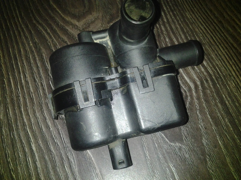
6 - Secondary air cut-off valve with built-in control valve;
7 - Electric air pump;
9 - Pressure sensor;
10 - To other consumers of rarefaction;
12 - Filler neck of the fuel tank with a connector for the fuel vapor recovery system;
13 - Valve cut-off coal adsorber;
14 - Coal adsorber;
15 - Fuel tank.
Petrol models
All petrol models must use unleaded petrol only. The engine management system operates in such a way as to get the most out of the engine while minimizing fuel consumption and exhaust emissions. The system of catching fuel vapors prevents them from getting out of the fuel tank into the atmosphere. An exhaust gas recirculation system was installed.
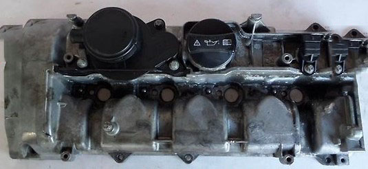
Crankcase ventilation system
To eliminate leakage of unburned hydrocarbons into the atmosphere, the engine is completely sealed. Gases and oil vapors formed in the crankcase enter the intake manifold through a strainer and burn in the cylinders along with the fuel.
Gases are removed from the crankcase due to the difference in pressure in the crankcase and the inlet pipeline (the pressure in the crankcase is higher).
catalytic converter
To reduce the amount of harmful emissions into the atmosphere on all gasoline models, a three-function catalytic converter is integrated into the exhaust system. The fuel injection control system has feedback, which includes an oxygen sensor. This sensor, installed in the exhaust system, constantly informs the control unit about the composition of the exhaust gases. Depending on the received data, the control unit corrects the quality of the mixture supplied to the combustion chambers and, thus, optimizes the combustion of the fuel.
A heating element is built into the lambda probe, which is switched on by the control unit through a special relay. The working surface of the lambda probe is sensitive to changes in the oxygen content in gases. Depending on the oxygen concentration, the sensor sends signals of different voltages. If the mixture is too rich - the oxygen content in the exhaust gases is very low, the sensor gives low voltage signals. The voltage increases as the mixture becomes leaner and the oxygen content of the gases increases. The converter works most efficiently with the optimal composition of the combustible mixture (14.7 parts of air per 1 part of fuel). At the optimum concentration of oxygen in the exhaust gases, a jump in voltage occurs at the sensor. This jump is the starting point for the control unit when adjusting the quality of the mixture.
Two sensors are installed. One is before, and the second is after the converter. This achieves a more accurate monitoring of the composition of the exhaust gases.
Exhaust gas recirculation system
The exhaust gas recirculation system helps to reduce the amount of NOx in the exhaust gases. To do this, a small part of the exhaust gases is fed into the intake manifold through a special valve. The valve of the recirculation system is controlled by the control unit.
Evaporative Emission System
To reduce the emission of unburned hydrocarbons into the atmosphere, a fuel recovery system is installed on all gasoline models. The filler neck of the fuel tank is hermetically sealed with a lid, a carbon adsorber is installed under the fuel tank. It collects fuel vapors that form in the tank while the car is parked and is stored there until the filter purge begins at the signal of the control unit. Then fuel vapors begin to be supplied through the purge valve(s) to the intake manifold, where they mix with the working mixture and then burn out in the usual way in the combustion chambers.
To ensure normal operation of the engine at idle and during warm-up, the control unit keeps the valve closed. This prevents unburned fuel from entering the converter (at higher idle speeds, the mixture is too rich). After the engine warms up, the valve begins to open and close, supplying fuel vapor to the intake tract.
Diesel models
The engine management system operates in such a way as to get the most out of the engine while minimizing fuel consumption and exhaust emissions. To further reduce the toxicity of gases, several additional systems are installed on the car. The crankcase ventilation system reduces gas leakage to the atmosphere from the engine lubrication system. The catalytic converter reduces the toxicity of exhaust gases. An exhaust gas recirculation system was installed.
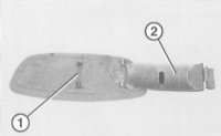
Controlled crankcase ventilation system
To eliminate leakage of unburned hydrocarbons into the atmosphere, the engine is completely sealed. Gases and oil vapors formed in the crankcase enter the intake manifold through a strainer and burn in the cylinders along with the fuel.
Gases are removed from the crankcase due to the pressure difference between the crankcase and the intake manifold (the pressure in the crankcase is higher). All diesel models are equipped with a ventilation valve. It is located on the head cover and controls the flow of gases from the crankcase.
Exhaust gas recirculation system
All diesel models also have an exhaust gas recirculation system. This system reduces the amount of NOx in the exhaust gases. To do this, a small part of the exhaust gases is fed into the intake manifold through a special valve. The valve of the recirculation system is controlled by the control unit.
The article is missing:
- High-quality repair photos
Source: http://auto-knigi.com/model/mb_c/6_4_3/