![P12 [2001 - 2008]](/uploads/Nissan_Primera_Primera_1.9_DCi_Sedan.jpg)

Tools:
- Pliers
- Open-end wrench - 13 mm
- Open-end wrench - 17 mm
- Nozzle on the collar - 10 mm
- Nozzle on the collar - 13 mm
- Nozzle on the collar - 17 mm
- Collar for end nozzle
- Hex key - 10 mm
- wire cutters
- Ruler
- probe
- Milling and grinding machine
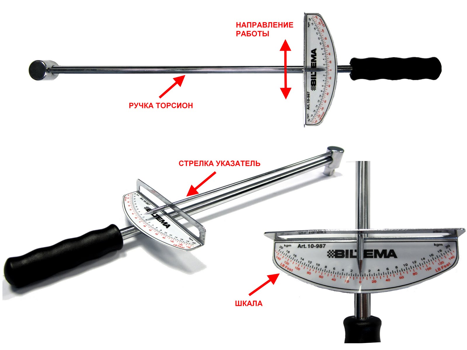
- torque wrench
Parts and consumables:
- Cylinder head gasket
- Coolant
- Container for coolant
- Motor oil
Notes:
If a leak of engine oil - or coolant is detected at the junction of the block head with the cylinder block, remove the head and replace its gasket. A leak can also occur due to warping of the block head due to overheating.
1. Reduce the pressure in the fuel system if you are doing work immediately after a trip.
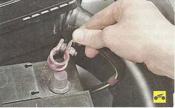
2. Disconnect a wire from the minus plug of the storage battery.
3. Drain the coolant.
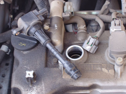
4. Remove ignition coils.
5. Set the piston of the 1st cylinder to the TDC position of the compression stroke. More details here .
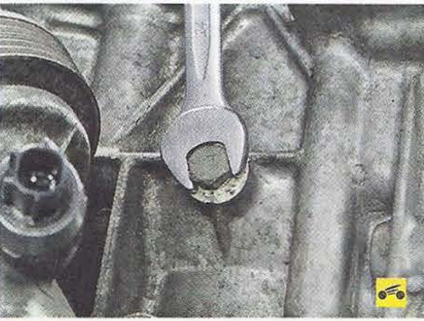
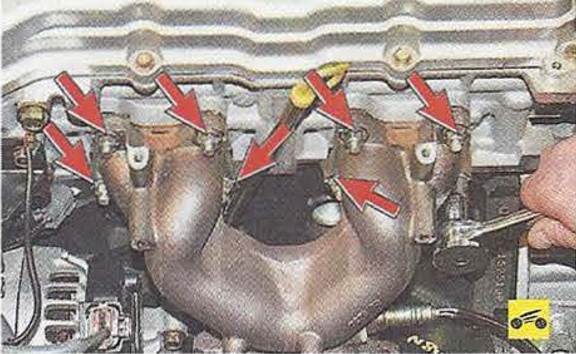
6. Turn away nuts of hairpins of fastening of a final collector to a head of the block of cylinders and disconnect a collector from a head.
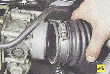
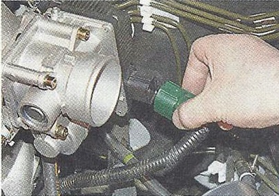
7. After loosening the clamp securing the air supply hose to the throttle assembly, remove the hose from the nozzle of the throttle assembly.
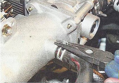
8. Compress antennae of a collar of a hose of system of ventilation of crankcase gases.
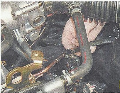
9. Disconnect a hose from a branch pipe of an inlet collector.
10. Similarly disconnect a hose of the vacuum amplifier of brakes.
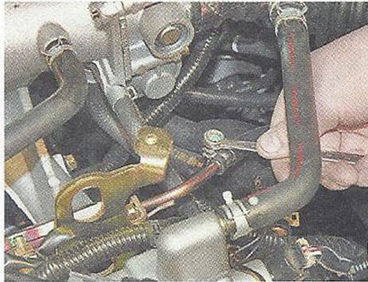
11. Squeeze the antennae of the clamps.
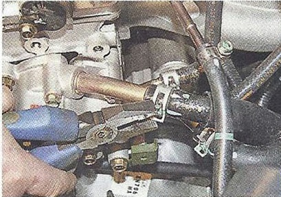
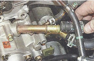
12. Disconnect the engine cooling system hoses from the nozzles on the cylinder head.
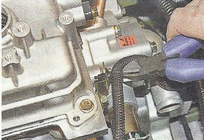
13. Snip the wire harness clamps to the brackets on the cylinder head and disconnect the harness from the clamp.
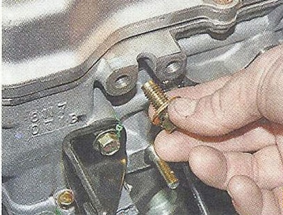
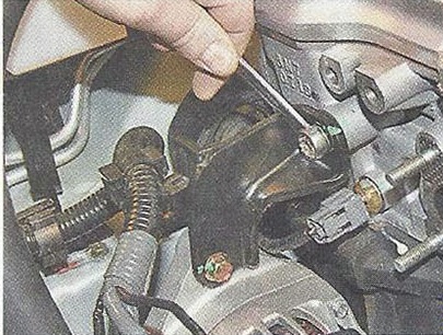
14. Turn out bolts of fastening of plugs of "mass" wires to a head of the block of cylinders.
15. Disconnect plugs with wires from a head of the block of cylinders.
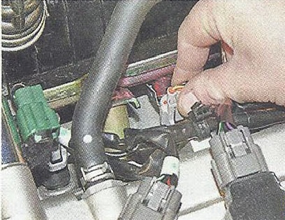
16. Press the clamps of the wiring harness pads and disconnect the pads from the terminals of the injectors, throttle assembly and coolant temperature sensor.
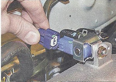
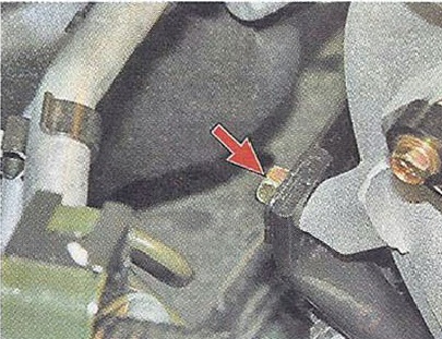
17. Press the plastic retainer of the canister purge valve wiring harness block and disconnect the block from the valve terminals.
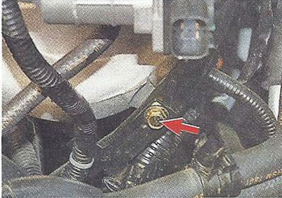
18. Squeeze the antennae of the collar of the inlet hose from the adsorber to the valve and remove the hose from the valve fitting.
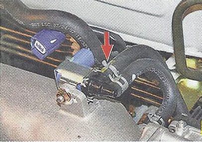
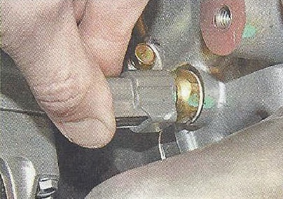
19. Loosen the clamp securing the fuel supply hose to the fuel rail.
20. Disconnect the hose from the ramp fitting.
21. Turn out a bolt of fastening of an arm of the generator to a head of the block of cylinders and take away an arm with the generator aside.
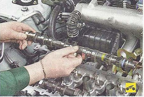
22. Remove camshafts.
23. Turn out bolts of fastening of the right and left support to an inlet collector.
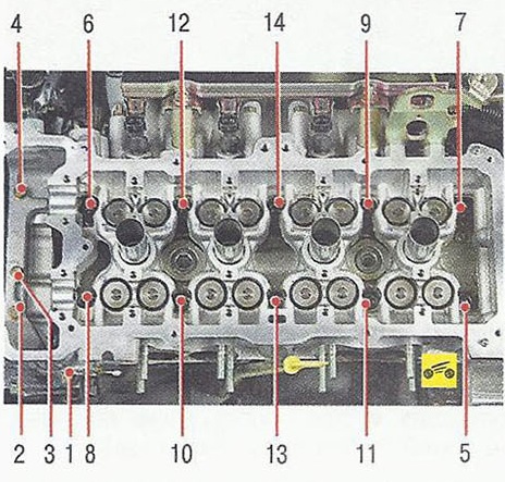
24. Loosen the fourteen bolts securing the cylinder head to the cylinder block in the sequence shown in the photo.
Notes:
Bolts of fastening of a head of the block of cylinders can be turned out only on the cold engine.
25. Remove the cylinder head from the engine.
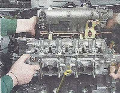
Note:
Remove the cylinder head with an assistant, as it is quite heavy.
26. Clean the mating surfaces of the head and block.
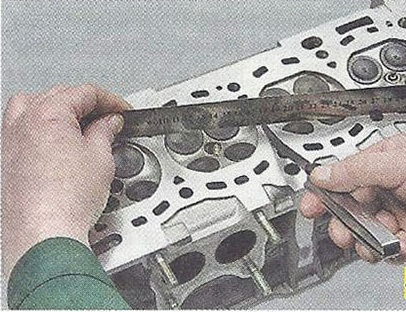
27. Check up a head of the block on lack of a buckling. To do this, placing the ruler with an edge on the surface of the head, first in the middle along, then across and diagonally, measure the gap between the surface of the head and the ruler with a feeler gauge. Grind the cylinder head if the clearance is greater than 0.1 mm.
28. Install the cylinder head in the reverse order of removal.
Notes:
Remove oil and coolant from the threaded holes of the cylinder head bolts that got there when the head was removed.
Be sure to install a new head gasket, do not reuse it.
Lubricate the bolts with engine oil.
Tighten the bolts on a cold engine in the order shown in the photo in six steps:
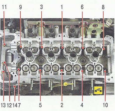
1 - tighten bolts 1-10 to 29 Nm.
2 - tighten bolts 1-10 to 58.8 Nm.
3 - loosen bolts 1-10 completely.
4 - tighten bolts 1-10 to 29.4 Nm.
5 - tighten bolts 1-10 by 50-55° - clockwise.
6 - tighten bolts 11-14 to 6.3-8.3 Nm.
29. Install the camshafts.
30. Install all removed parts in the reverse order of removal.
The article is missing:
- Tool photo
- Photo of parts and consumables
- High-quality repair photos
Source: Nissan Primera P12 Operation, Maintenance and Repair Manual. Publishing house "Third Rome".