SQR481FC engine structure for Chery Tiggo in detail:
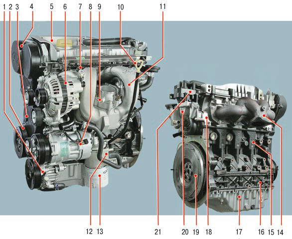
1 - power steering pump;
2 - a pulley of a drive of auxiliary units;
3 - the lower cover of the gas distribution mechanism drive;
4 - upper cover of the gas distribution mechanism drive;
5 - cylinder head cover;
6 - generator;
7 - fuel rail;
8 - air conditioning compressor;
9 - throttle assembly;
10 - intake manifold;
11 - oil level indicator (dipstick);
12 - heat exchanger of the lubrication system;
13 - oil filter;
14 - exhaust manifold;
15 - cylinder block;
16 - amplifier of the cylinder block;
17 - oil sump;
18 - cylinder head;
19 - flywheel;
20 - thermostat housing;
21 - ignition coil.
SQR481FC engine timing gear:
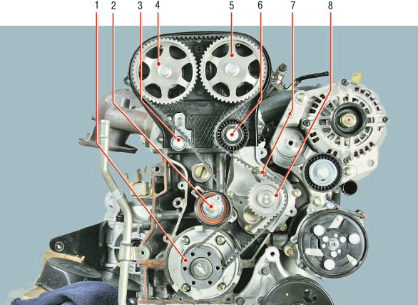
1 - crankshaft toothed pulley;
2 - tension roller of the gas distribution mechanism drive;
3, 6 - intermediate rollers of the gas distribution mechanism drive;
4 - toothed pulley of the exhaust camshaft;
5 - toothed pulley of the intake camshaft;
7 - timing belt;
8 - a pulley of a drive of auxiliary units.
On Chery Tiggo cars designed for the Russian market, transversely located gasoline engines are installed: Acteco SQR481FC (DOHC, 118 hp) with a working volume of 1.8 liters, Mitsubishi 4G63S4M with a volume of 2.0 liters (SOHC, 125 hp) and Mitsubishi 4G64S4M with a volume of 2.4 liters (SOHC, 130 hp).
All engines are four-stroke, four-cylinder, injection, liquid-cooled.
The SQR481FC engine with an overhead two five-point camshafts has four valves per cylinder. The camshafts are driven by a reinforced toothed belt. Belt tension is provided by a tension roller.
Clearances in the valve drive are eliminated by hydraulic lifters connected by channels to the lubrication system.
The cylinder head is made of an aluminum alloy with a transverse cylinder purge pattern (intake and exhaust ports are located on opposite sides of the head). Valve seats and valve guides are pressed into the heads. The inlet and outlet valves are equipped with one spring, fixed through the plate with two crackers.
The valves are driven by camshafts through levers resting with one shoulder on hydraulic lifters screwed into the block head, and with the other on the upper ends of the valve stems.
The cylinder block is a single casting that forms the cylinders, the cooling jacket, the upper part of the crankcase and five crankshaft bearings, made in the form of crankcase baffles. The block is made of special nodular cast iron with cylinders bored directly into the block body. To increase the rigidity of the cylinder block, an amplifier is installed in its lower part, made in one piece with the main bearing caps.
Special bosses, flanges and holes for fastening parts, assemblies and assemblies, as well as channels of the main oil line are made on the cylinder block. The bottom of the cylinder block is closed by a cast aluminum alloy oil sump. The plane of the connector of the cylinder block and the oil sump is sealed with a sealant, there is no removable gasket.
The crankshaft rotates in main bearings with thin-walled steel liners with an anti-friction layer.
The axial movement of the crankshaft is limited by two half rings installed in the groove of the bed of the fourth main bearing.
A flywheel, cast from cast iron, is mounted on the rear end of the crankshaft and is secured by six bolts. A toothed rim is pressed onto the flywheel to start the engine with a starter.
The pistons are made of aluminum alloy. On the cylindrical surface of the piston head there are annular grooves for the oil scraper and two compression rings.
Piston pins are installed in the piston bosses with a gap and pressed with an interference fit into the upper connecting rod heads.
Steel connecting rods, forged, with an I-section rod are connected by their lower heads to the crankshaft connecting rod journals through thin-walled liners, the design of which is similar to the main ones.
Combined lubrication system.
The closed crankcase ventilation system does not communicate directly with the atmosphere, therefore, simultaneously with the suction of gases in the crankcase, a vacuum is formed in all engine operating modes, which increases the reliability of various engine seals and reduces the emission of toxic substances into the atmosphere.
When the engine is running, crankcase gases are sucked into the intake manifold through a hose connected to the fitting on the head cover and the crankcase ventilation system valve. The valve opens depending on the vacuum in the intake manifold and thus regulates the flow of crankcase gases.
The cooling system is sealed, with an expansion tank, and consists of a cooling jacket made in casting and surrounding the cylinders in the block, the combustion chamber and gas channels in the cylinder head.
Forced circulation of the coolant is provided by a centrifugal water pump driven by a timing belt. To maintain a normal operating temperature of the coolant, a thermostat is installed in the cooling system, which closes the large circle of the system when the engine is cold and the coolant temperature is low.
The power system consists of an electric fuel pump installed in the fuel tank, fuel pressure regulator, fuel filter, throttle assembly, injectors and fuel lines, and also includes an air filter.
The microprocessor-based ignition system consists of an ignition coil, high-voltage wires and spark plugs. The ignition coil is controlled by the electronic engine control unit. The ignition system does not require maintenance and adjustment during operation.
The power unit (engine with a gearbox, clutch and main gear) is installed on four supports with elastic rubber elements - two upper side (right and left), which perceive the main mass of the power unit, and two lower (rear and front), compensating the torque from transmissions and loads arising from starting, acceleration and braking.
Helpful hints:
With a certain amount of skill and care, many malfunctions of the engine and its systems can be fairly accurately identified by the color of the smoke coming out of the exhaust pipe. Blue smoke indicates that oil has entered the combustion chambers, and constant smoke is a sign of severe wear of the parts of the cylinder-piston group.
The appearance of smoke during gas changes, after prolonged cranking with the starter, after a long idle run or immediately after engine braking, usually indicates wear on the valve stem seals. Black smoke - too rich mixture due to malfunction of the engine management system or injectors. Gray or thick white smoke mixed with moisture (especially after engine overheating) means that coolant has entered the combustion chamber through a damaged cylinder head gasket. If this gasket is severely damaged, the liquid sometimes gets into the oil sump, the oil level rises sharply, and the oil itself turns into a cloudy whitish emulsion. White smoke (steam) is normal when the engine is cold in wet or cold weather.
Quite often, you can see a car with an open hood standing in the middle of a city traffic jam, emitting clouds of steam. Overheat. It is better, of course, not to allow this, often glancing at the temperature gauge.
But no one is safe from the fact that a thermostat, electric fans may unexpectedly fail, or a coolant just leaks. If you miss a moment of overheating, don't panic or aggravate the situation. Overheating is not so terrible as its possible consequences. Never turn off the engine right away - it will get heatstroke and, after cooling down, will refuse to start at all. After stopping, let it idle, then the fluid circulation will remain in the system. Turn on the heater at maximum power and open the hood. If possible, pour cold water on the radiator.
Once the temperature has dropped, stop the engine. But never immediately open the radiator cap - on an overheated engine, a geyser from under an open plug is provided to you. Take your time, let everything cool down, so you keep the health of the car and your own health.
Almost all the instructions for the car contain a recommendation when starting the engine, be sure to squeeze the clutch. This recommendation is justified only in case of starting in severe frost, so as not to waste the battery energy on turning the shafts and gears of the gearbox in thickened oil. In other cases, this is just a recommendation so that the car does not move if the gear is on for forgetfulness. This technique is harmful to the engine, since when the clutch is squeezed out, a significant force is transmitted through it to the thrust bearing of the crankshaft, and when starting (especially cold), lubricant does not flow to it for a long time. The bearing wears out quickly, the crankshaft receives axial play, and starting off is accompanied by strong vibration. In order not to spoil the engine,
Source: http://chery-tiggo.dv13.ru/dvigatel/
![T11 [2005 - 2014]](/uploads/Chery_Tigo_T11_2005_-_2014_.jpg)