Notes:
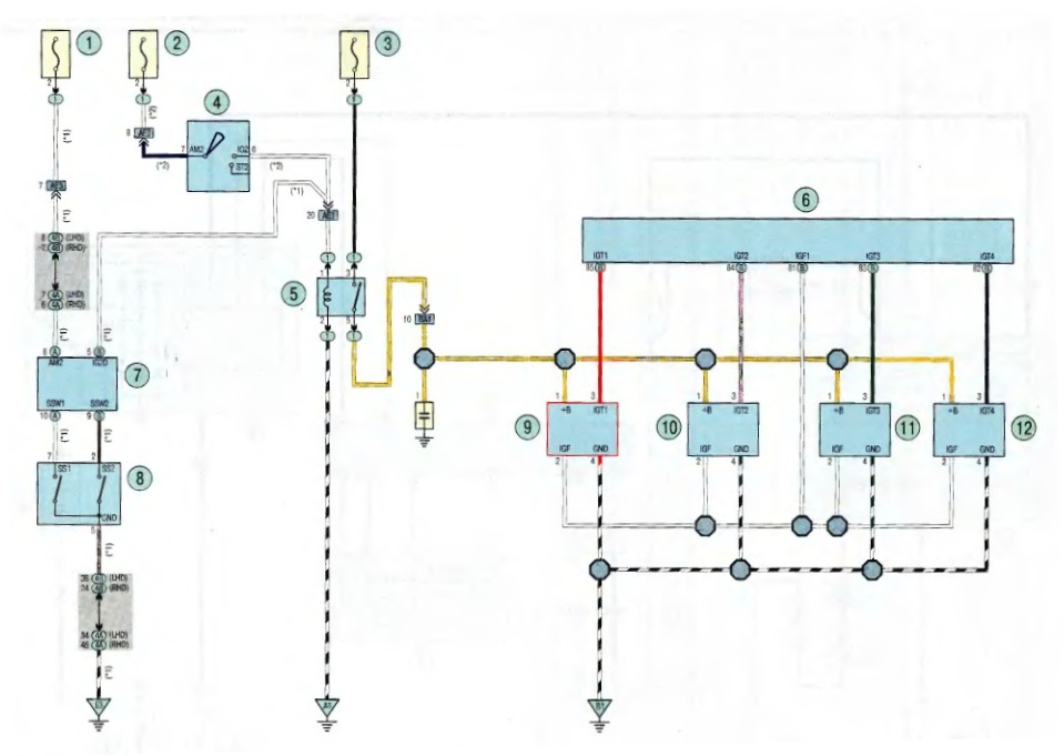
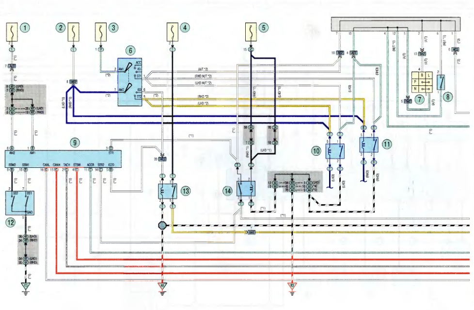
Below are wiring diagrams for connecting the immobilizer system to understand the functionality and dependency of the circuits when repairing/replacing the relevant parts.
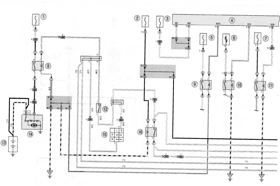
Scheme 1. Immobilizer system connections:
1 - fuse AM2 (30 A):
2 - IGN fuse (7.5 A);
3 - fuse AM2-2 (7.5 A),
4 - electronic block of the body;
6 - fuse ACC-B (25 A),
6 - fusible insert ALT (120 A);
7 - fuse IG2 (15 A);
8 - relay ST;
9 - ACC relay;
10 - relay IG1:
11 - relay IG2;
12 - starter blocking switch;
13 - battery;
14 - starter;
15 - selector lever switch;
16 - relay ST CUT.
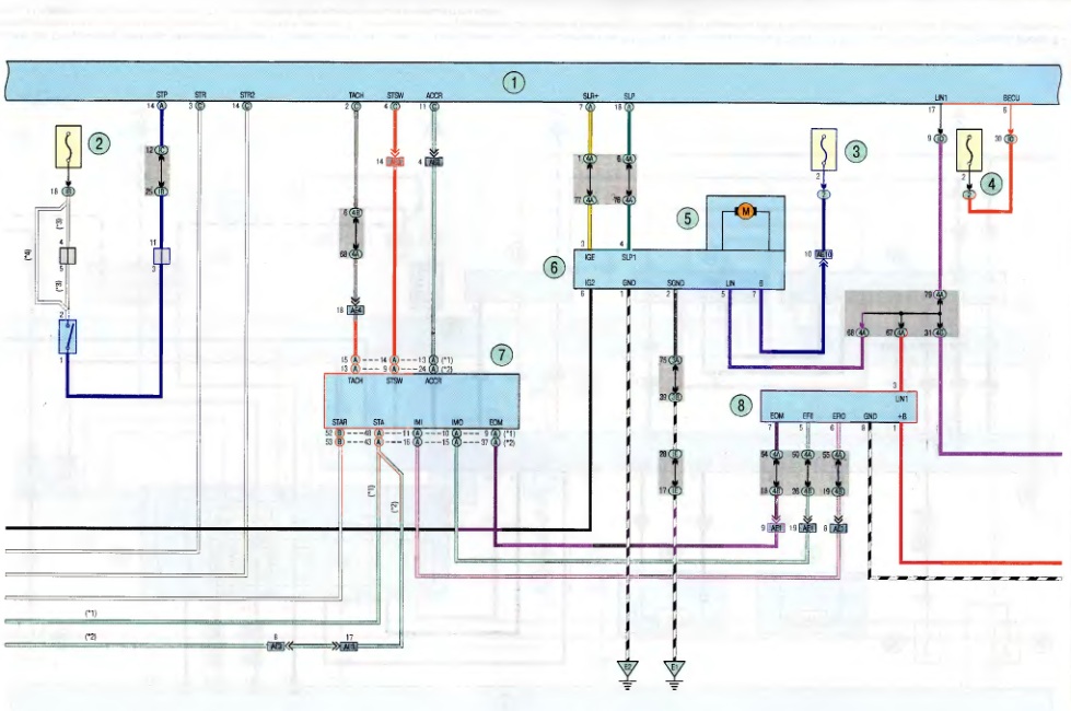
Scheme 2. Connections of the immobilizer system :
1 - electronic block of the body;
2 - STOP fuse (10 A);
3 - STR LOCK fuse (20 A);
4 - fuse ECU-B (10 A);
5 - electric power steering motor reducer;
6 - electronic control unit for the electric power steering system;
7 - electronic engine control unit;
8 - diagnostic block.
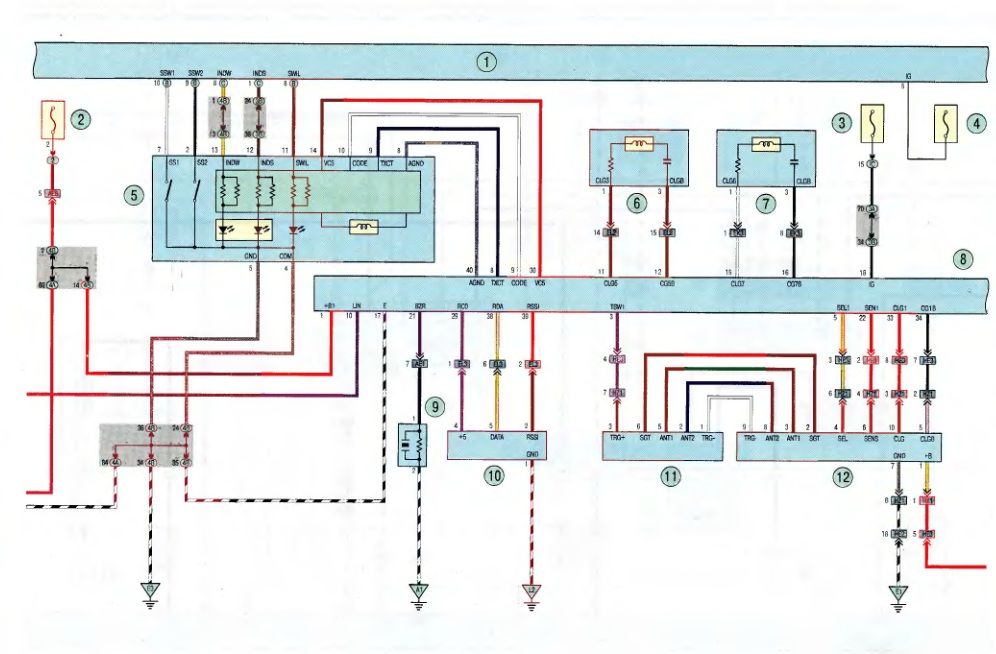
Scheme 3. Connections of the immobilizer system:
1 - electronic block of the body;
2 - fuse;
3 - IGN fuse (10 A);
4 - fuse ECU-IG1 (10 A);
5 - key unlock switch;
6 - electric key of the immobilizer system;
7 - signal amplifier;
8 - electronic steering lock control unit,
9 - remote door lock system receiver;
10 - control block;
11 - sensor in the outer door handle,
12 - electronic block for identifying the incoming signal.
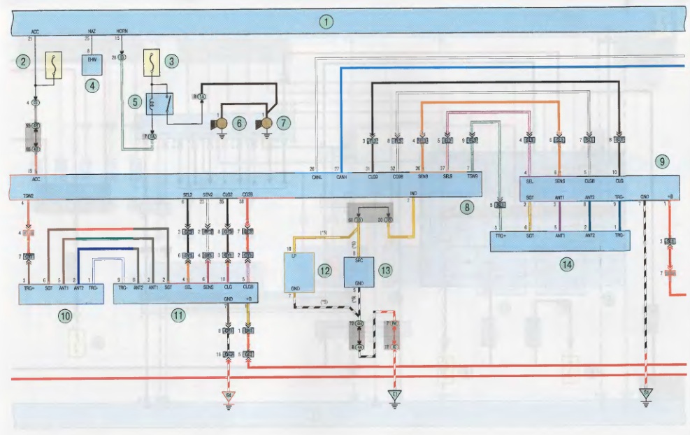
Scheme 4. Connections of the immobilizer system :
1 - electronic block of the body;
2 - ACC fuse (7.5 A);
3 - HORN fuse (10 A);
4 - FLSH relay;
5 - HORN relay;
6, 7 - sound signals;
8 - electronic steering lock control unit;
9 - electronic block of the ignition switch (lock);
10, 11 - electronic block of the ignition key;
12 - coil of an electronic ignition key;
13 - amplifier of the electronic ignition key;
14 - sensor in the outer door handle.
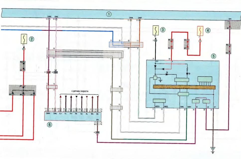
Diagram 5. Immobilizer system connections:
1 - electronic block of the body;
2, 4 - ECU-B fuse (10 A);
3 - fuse GAUGE 2 (7.5 A);
5 - instrument cluster;
6 - electronic transmission control unit.
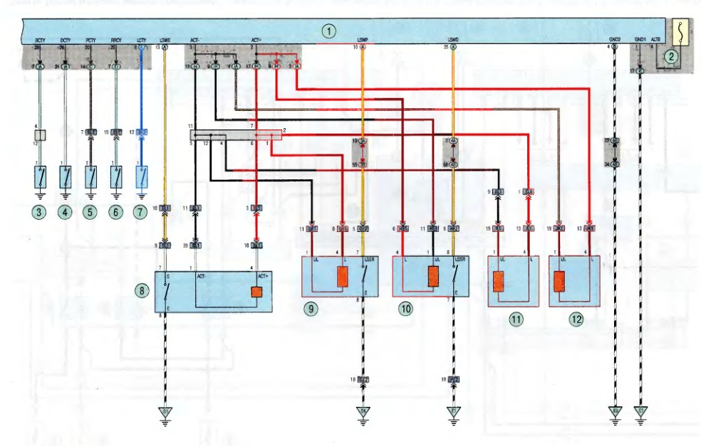
Scheme 6. Connections of the immobilizer system :
1 - electronic block of the body;
2 - DOOR fuse (25 A);
3 - limit switch of the left front door;
4 - limit switch of the right front door;
5 - limit switch of the right rear door;
6 - limit switch of the left rear door;
7 - tailgate limit switch;
8 - tailgate lock;
9 - lock of the right front door;
10 - lock of the left front door;
11 - lock of the right rear door;
12 - left rear door lock.
Source: TOYOTA RAV4 Operation and Repair Manual since 2005 (Third Rome)
![2 generation [2000 - 2003]](/uploads/toyota-rav-4-ii-11109.jpg)
![3 generation [2005 - 2009]](/uploads/Toyota_RAV_4_-_2006_-_2009_.jpg)
![4 generation [2012 - 2015]](/uploads/Toyota_RAV_4_-_2012-2015_.jpg)
