![1 generation [2012 - 2017]](/uploads/Lada_Largus_2012-2015_.jpg)

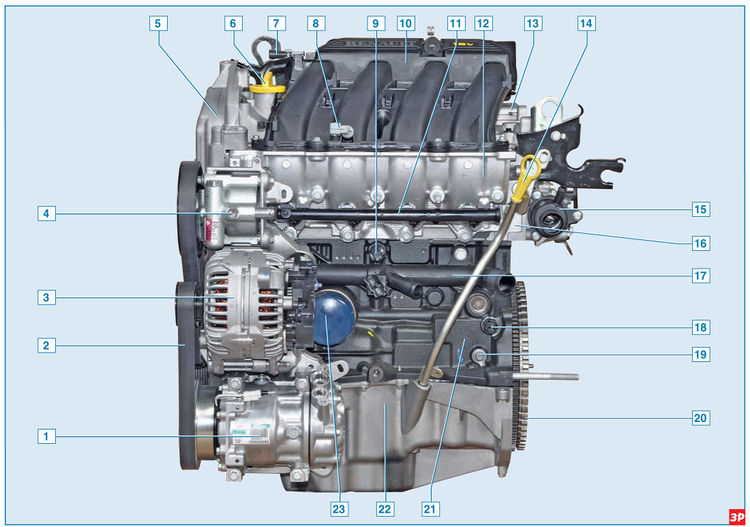
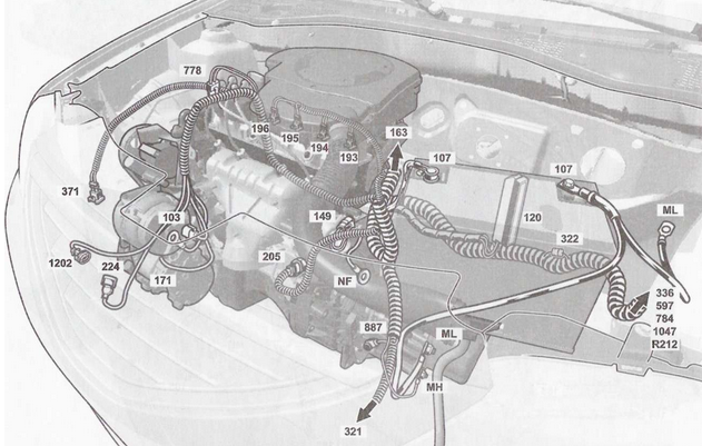
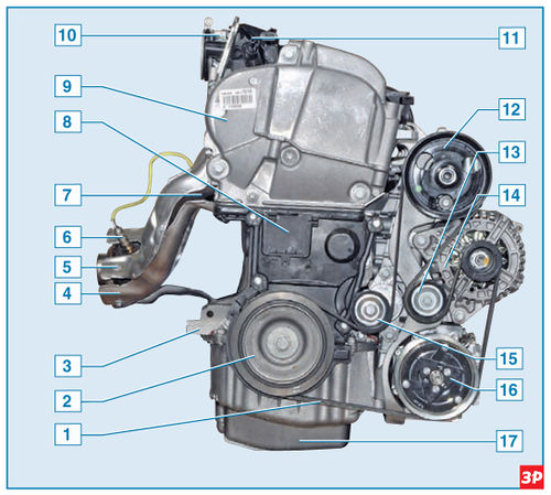
Engine (front view in vehicle direction)
1 - air conditioning compressor;
2 – a belt of a drive of auxiliary units;
3 - generator;
4 - power steering pump;
5 – the top cover of a drive of the gas-distributing mechanism;
6 - oil filler cap;
7 - absolute air pressure sensor;
8 - intake air temperature sensor;
9 - knock sensor;
10 - receiver;
11 - fuel rail with nozzles;
12 - inlet pipeline;
13 – a cover of a head of the block of cylinders;
14 - oil level indicator;
15– thermostat case;
16 – a head of the block of cylinders;
17 – a pipe of the pump of a cooling liquid;
18 - low oil pressure indicator sensor;
19 - plug;
20 - flywheel;
21 - cylinder block;
22 - oil pan;
23 - oil filter.
The K4M engine is a gasoline, four-stroke, four-cylinder, in-line, sixteen-valve, with an overhead arrangement of two camshafts. The order of operation of the cylinders: 1-3-4-2, counting - from the flywheel. Power system - distributed fuel injection (Euro 4 toxicity standards). The engine with a gearbox and clutch form a power unit - a single unit, fixed in the engine compartment on three elastic rubber-metal bearings. The right support is attached to the top cover of the gas distribution mechanism drive, and the left and rear ones are attached to the gearbox housing.
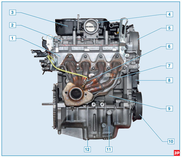
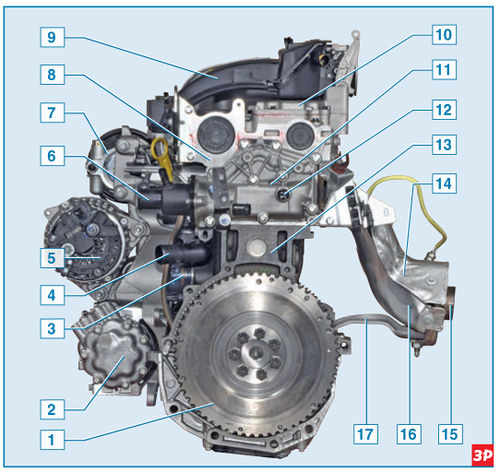
Engine (rear view in the direction of travel of the vehicle)
1 – a head of the block of cylinders;
2 – a cover of a head of the block of cylinders;
3 - receiver;
4 - throttle assembly;
5 – the top cover of a drive of the gas-distributing mechanism;
6 – control oxygen concentration sensor;
7 - exhaust manifold;
8 - the lower cover of the gas distribution mechanism drive;
9 - block of cylinders;
10 – a belt of a drive of auxiliary units;
11 - oil pan;
12 - oil drain plug.
On the front of the engine (in the direction of the car) are located: inlet pipeline; oil filter; oil level indicator; low oil pressure indicator sensor; fuel rail with injectors; knock sensor; coolant pump inlet pipe; generator; power steering pump; air conditioning compressor.
Behind on the engine are located: the case of the air filter with the regulator of idling; exhaust manifold with a control oxygen concentration sensor; starter.
On the right is the coolant pump; timing gear and coolant pump drive (toothed belt); drive of auxiliary units (poly V-belt).
On the left are: flywheel; crankshaft position sensor; thermostat; thermostat housing with coolant temperature sensor.
Above - coils and spark plugs; oil filler neck; a receiver with absolute pressure and intake air temperature sensors, a throttle assembly with a throttle position sensor.
Engine (right side view in vehicle direction)
1 – a belt of a drive of auxiliary units;
2 – a pulley of a drive of auxiliary units;
3 - block of cylinders;
4 - the lower heat shield of the exhaust manifold;
5 - the upper heat shield of the exhaust manifold;
6 – control oxygen concentration sensor;
7 - exhaust manifold;
8 - the lower cover of the gas distribution mechanism drive;
9 – the top cover of a drive of the gas-distributing mechanism;
10 - throttle assembly;
11 - receiver;
12 – a pulley of the pump of the hydraulic booster of a steering;
13 - belt support roller;
14 - generator;
15 - belt tensioner roller;
16 – a pulley of the compressor of the conditioner;
17 - oil pan.
The engine cylinder block is cast iron, the cylinders are bored directly in the block.
In the lower part of the cylinder block there are five crankshaft main bearing supports with removable covers, which are attached to the block with special bolts. The holes in the cylinder block for the bearings are machined with the covers installed, so the covers are not interchangeable and are marked on the outer surface to distinguish them (the covers are counted from the flywheel side). On the end surfaces of the middle support, sockets are made for thrust half rings that prevent axial movement of the crankshaft. To cool the pistons during engine operation, their bottoms are washed from below with engine oil through special nozzles pressed into the cylinder block in the area of the second and fourth supports (on both sides of the supports) of the main bearings.
Crankshaft with five main and four connecting rod journals. The shells of the main and connecting rod bearings of the crankshaft are steel, thin-walled with an anti-friction coating applied to the working surfaces of the shells. The shaft is equipped with four counterweights integral with the shaft. Channels are made in the necks and cheeks of the shaft to supply oil from the main journals to the connecting rod journals. At the front end (toe) of the crankshaft are installed: an oil pump drive sprocket, a timing gear drive pulley (timing) and an auxiliary drive pulley. The toothed pulley is fixed on the shaft with a protrusion that fits into a groove on the toe of the crankshaft. Similarly, the auxiliary drive pulley is fixed on the shaft.
Engine (left view in vehicle direction)
1 - flywheel;
2 - air conditioner compressor;
3 - oil filter;
4 - inlet pipe of the coolant pump;
5 - generator;
6 - thermostat housing;
7 - power steering pump;
8 – a head of the block of cylinders;
9 - receiver;
10 – a cover of a head of the block of cylinders;
11 – a cover of a jacket of cooling of a head of the block of cylinders;
12 - coolant temperature sensor;
13 - cylinder block;
14 - the upper heat shield of the exhaust manifold;
15 - exhaust manifold;
16 - lower heat shield of the exhaust manifold;
17 - exhaust manifold bracket.
The crankshaft is sealed with two oil seals, one of which (from the timing drive side) is pressed into the cylinder block cover, and the other (from the flywheel side) into the socket formed by the surfaces of the cylinder block and the main bearing cover. A flywheel is attached to the crankshaft flange with seven bolts. It is cast from cast iron and has a pressed steel crown for starting the engine with a starter. In addition, a ring gear for the crankshaft position sensor is cut into the flywheel.
Connecting rods - forged steel, I-section, processed together with covers. The covers are attached to the connecting rods with special bolts and nuts. With their lower (crank) heads, the connecting rods are connected through liners to the connecting rod journals of the crankshaft, and the upper heads are connected through piston pins to the pistons. Piston pins - steel, tubular section. The pin, pressed into the upper head of the connecting rod, rotates freely in the piston bosses. The pistons are made of aluminum alloy. The piston skirt has a complex shape: barrel-shaped in longitudinal section, and oval in transverse section. Three grooves for piston rings are machined in the upper part of the piston. The two upper piston rings are compression rings, and the lower one is oil scraper.
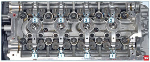
cylinder head
1 - inlet valves;
2 - exhaust valves.
The cylinder head is cast from aluminum alloy, common to all four cylinders. The cylinder head is centered on the block with two bushings and secured with ten screws. A non-shrink metal gasket is installed between the block and the head. On opposite sides of the cylinder head are the intake and exhaust ports. Spark plugs are installed in the center of each combustion chamber. The valves are steel, in the cylinder head are arranged in two rows, V-shaped, two intake and two exhaust valves for each cylinder. The intake valve plate is larger than the exhaust valve. Seats and valve guides are pressed into the cylinder head. Valve guides are fitted with oil caps on top of the valve guides. The valve closes under the action of a spring. Its lower end rests on the puck, and its upper end rests on the plate, which is held by two biscuits. The folded crackers have the shape of a truncated cone on the outside, and on the inside they are equipped with thrust collars that enter the groove on the valve stem.
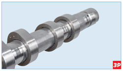
The cams are pressed onto the camshaft.
Two camshafts are installed at the top of the cylinder head. One shaft drives the intake valves of the gas distribution mechanism, and the other drives the exhaust valves. Eight cams are made on each shaft - an adjacent pair of cams simultaneously controls the valves (inlet or outlet) of each cylinder. A design feature of the camshaft is that the cams are pressed onto the tubular shaft.
Supports (beds) of camshafts (six bearings for each shaft) are detachable - located in the cylinder head and in the head cover. Camshaft drive - toothed belt from the crankshaft pulley. On each camshaft, on the side of the toothed pulley, a thrust flange is made, which, during assembly, enters the groove of the cylinder head, thereby preventing axial movement of the shaft. The camshaft pulley is fixed on the shaft not with a tight fit, key or pin, but only due to the friction forces that occur on the end surfaces of the pulley and shaft when the pulley fastening nut is tightened. The toe of the camshaft is sealed with an oil seal, put on the neck of the shaft and pressed into the socket formed by the surfaces of the cylinder head and the head cover.
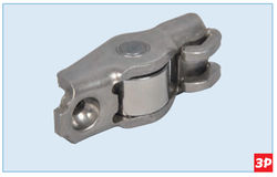
valve lever
The valves are driven from the camshaft cams through the valve levers. To increase the life of the camshaft and valve levers, the cam of the shaft acts on the lever through a roller that rotates on the axis of the lever.
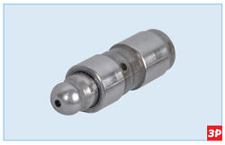
Valve lever hydraulic support
The hydraulic bearings of the valve levers are installed in the sockets of the cylinder head. The oil inside the hydraulic support comes from the line in the cylinder head through the hole in the hydraulic support housing. The hydraulic support automatically ensures backlash-free contact of the camshaft cam with the valve lever roller, compensating for wear on the cam, lever, valve stem end face, seat chamfers and valve disc.
At one end, the lever rests on the spherical head of the hydrosupport, and at the other end it acts on the end of the valve stem.
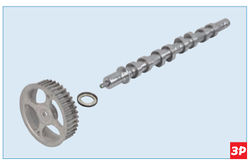
Camshaft with toothed pulley and oil seal.
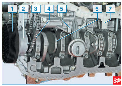
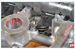
Oil pump drive (sump removed)
1 - auxiliary drive pulley;
2 – a cover of the block of cylinders;
3 - drive sprocket of the pump drive;
4 - drive chain;
5 - oil pump;
6 - crankshaft;
7 - cylinder block.
Engine lubrication - combined. Under pressure, oil is supplied to the main and connecting rod bearings of the crankshaft, camshaft bearings and hydraulic bearings of the valve levers. Other engine components are splash lubricated. The pressure in the lubrication system is created by a gear oil pump located in the oil pan and attached to the cylinder block. The oil pump is driven by a chain drive from the crankshaft. The drive sprocket of the pump drive is mounted on the crankshaft under the cylinder block cover. A cylindrical belt is made on the sprocket, along which the crankshaft front oil seal works. The sprocket is mounted on the crankshaft without tension and is not fixed with a key. When assembling the engine, the drive sprocket of the pump drive is clamped between the timing gear pulley and the shoulder of the crankshaft as a result of tightening the package of parts with the accessory drive pulley mounting bolt. The torque from the crankshaft is transmitted to the sprocket only due to the frictional forces between the end surfaces of the sprocket, the toothed pulley and the crankshaft. When loosening the bolt securing the accessory drive pulley, the oil pump drive drive sprocket may begin to rotate on the crankshaft and fall.
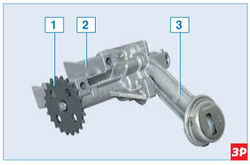
Oil pump
1 - driven sprocket of the drive;
2 - pump casing;
3 - cover of the pump housing with an oil receiver.
The oil receiver is made in one piece with the cover of the oil pump housing. The cover is fastened with five screws to the pump body. The pressure reducing valve is located in the cover of the pump housing and is kept from falling out by a spring retainer. The oil from the pump passes through the oil filter and enters the main oil line of the cylinder block. Oil filter - full-flow, non-separable. From the main line, oil flows to the crankshaft main bearings, piston cooling nozzles, and then (through the channels in the crankshaft) to the connecting rod bearings of the shaft. Through two vertical channels in the cylinder block, oil from the main line is supplied to the cylinder head - to the extreme supports of the camshafts from the side of the plugs and the valve hydraulic supports. Through grooves and drillings in the extreme bearing journals of the camshafts, oil enters the shafts and then through drillings in other shaft journals to the rest of the camshaft bearings. From the cylinder head, oil flows through vertical channels into the engine sump. The crankcase ventilation system is a closed, forced type. Gases that have penetrated from the combustion chambers of the cylinders through the piston rings into the crankcase of the engine enter through the channels in the block and the cylinder head into the head cover. After passing through the oil separator located in the cylinder head cover, crankcase gases are cleaned of oil particles and then flow through the air filter housing, throttle assembly, receiver and inlet pipeline into the engine cylinders. Control, power, cooling and exhaust systems are described in the relevant chapters.
Source: http://wiki.zr.ru/55-2_Largus