![2 generation [2004 - 2008]](/uploads/Ford_Focus_2_2004_-_2008_.jpg)
![3 generation [2011 - 2017]](/uploads/Ford_Focus_3_2011-2015_.jpg)

Ford Focus III cars for the Russian market are equipped with transverse four-stroke gasoline engines with in-line vertical arrangement of cylinders and liquid cooling: 1.6 l Duratec Ti-VCT with variable valve timing (105 hp);
1.6 l Duratec Ti-VCT with variable valve timing (125 hp); 2.0 L Duratec Ti-VCT with variable valve timing (150 hp).
All engines with overhead two camshafts have four valves per cylinder. The camshafts of the 2.0 liter engines are driven by a lamellar chain, the tension of which is provided by an automatic tensioner. The drive of the gas distribution mechanism of engines with a volume of 1.6 liters is carried out by a toothed belt. Belt tension is provided by a tension roller spring. On all motors, the valves are driven directly from the camshafts through cylindrical pushers, which simultaneously serve as adjusting elements for clearances in the drive.
The cylinder head is made of aluminum alloy according to the transverse cylinder scavenging pattern (inlet and outlet channels are located on opposite sides of the head). Seats and valve guides are pressed into the head. The intake and exhaust valves are equipped with a single spring, fixed through the plate with two crackers. The block head is centered on the block with two bushings and attached with ten bolts. A non-shrink metal-reinforced gasket is installed between the block and the head. In the upper part of the cylinder head, there are five bearing supports for two camshafts. The lower parts of the supports are made in one piece with the cylinder head, and the upper parts (covers) are bolted to the head. The holes of the supports are processed complete with covers, so the covers are not interchangeable, each of them is marked with a serial number. On engines
The 1.6L Duratec Ti-VCT front mounts are supported by a dynamic camshaft caliper, which at the same time keeps the camshafts from moving axially.
The cylinder block is a single casting of special high-strength cast iron, forming the cylinders, the cooling jacket, the upper part of the crankcase and five crankshaft bearings made in the form of crankcase partitions. cylinders
bored directly into the body of the block. In the lower part of the block, there are five beds of main bearings with removable covers bolted to the block. The main bearing caps are machined complete with the block and are not interchangeable. In the bearing beds (in the upper parts of the bearings) there are oil outlets for lubricating the main bearings, and through holes into which ball valves with nozzles are pressed through which oil is sprayed onto the piston bottoms and cylinder walls. On the cylinder block, special lugs, flanges and holes for fastening parts, assemblies and assemblies, as well as channels of the main oil line are made.
The crankshaft, made of ductile iron, rotates in main bearings equipped with thin-walled steel liners with an anti-friction layer. The upper liners installed in the cylinder block have a groove on the inner surface and a through slot through which oil flows from the outlet of the oil channel to the ball valve with a nozzle. There are no grooves or slots in the bottom liners. The axial movement of the crankshaft is limited by two identical thrust half rings. A flywheel is attached to the rear end of the crankshaft with six bolts. At the front end of the crankshaft, a timing gear drive pulley and an auxiliary drive pulley are installed.
The short skirted pistons are made of aluminum alloy. On the cylindrical surface of the piston head there are annular grooves for two compression and oil scraper rings. Six drillings in the groove of the oil scraper ring are designed to drain the oil removed by the ring from the cylinder walls. Two of these holes bring oil to the piston pin.
Piston pins of a tubular section are installed in the piston bosses with a gap and are pressed with an interference fit into the upper heads of the connecting rods, which are connected with their lower heads to the connecting rod journals of the crankshaft through thin-walled liners, the design of which is similar to the main liners.
Connecting rods are steel, forged, with an I-section rod. Connecting rods are processed complete with covers. In order not to confuse them during assembly, the serial number of the cylinder is applied to the side surfaces of the connecting rods and covers.
Camshafts are cast, cast iron.
The gas distribution mechanism is
closed with a plastic cylinder head cover. It has an oil separator for the crankcase ventilation system.
Combined lubrication system.
From below, an oil sump cast from an aluminum alloy is attached to the cylinder block. The oil sump flange is sealed with FORD WSE-M4G323-A4 gasket. The crankcase has an oil drain hole closed with a screw plug.
The oil filter is full-flow, non-separable, with bypass and anti-drainage valves.
The crankcase ventilation system is closed, forced, with the removal of crankcase gases through the oil separator into the air filter cavity.
The engine cooling system is sealed, with an expansion tank.
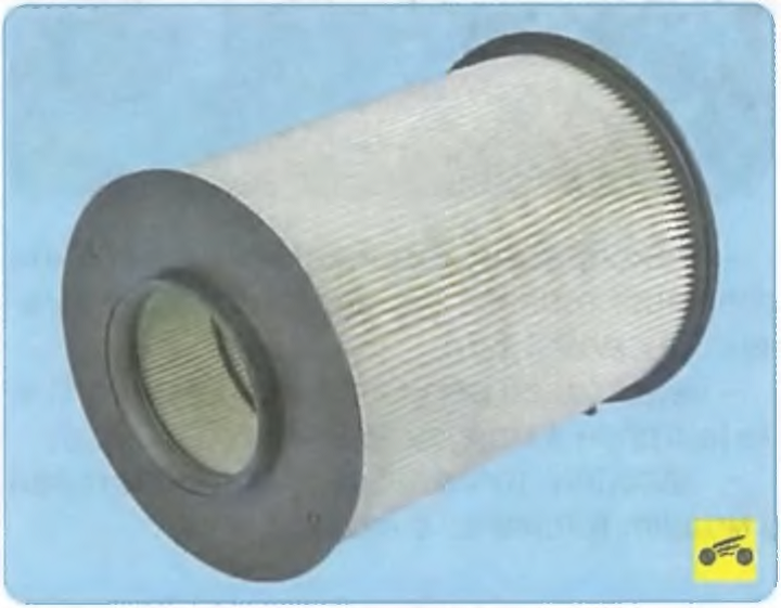
The engine power supply system consists of an electric fuel pump installed in the fuel tank, a throttle assembly, a fine fuel filter and a fuel pressure regulator installed in the fuel pump module, a fuel pressure pulsation compensator, injectors and fuel lines, and also includes an air filter.
The exhaust gas recirculation system with a recirculation valve driven by a stepper motor, according to the signals of the electronic unit of the engine management system, bypasses part of the exhaust gases into the intake manifold. This achieves a reduction in the toxicity of vehicle emissions and compliance with modern environmental standards.
The ignition system is microprocessor-based and consists of an ignition coil, high voltage wires and spark plugs. The ignition coil is controlled by the electronic engine control unit. The ignition system during operation does not require maintenance and adjustment.
NOTE
On 2.0 liter engines, a separate ignition coil is installed on each candle.
The engine management system includes an electronic control unit (controller), temperature and absolute pressure sensors in the intake manifold, throttle position, coolant temperature, crankshaft position, camshaft position, outside air temperature, oxygen concentration (control and diagnostic), accelerator, brake and clutch pedal positions, detonation, as well as actuators, connectors and fuses.
The power unit (engine with gearbox, clutch and final drive) is mounted on three supports with elastic rubber elements: two front ones, which take the bulk of the power unit, and a rear one, which compensates for the torque from the transmission and the loads that occur when the car starts from a standstill, acceleration and braking.
A distinctive feature of the 2.0 l Duratec Ti-VCT engines is a plastic intake manifold (Fig. 5.1) of variable length with additional swirl flaps at the inlet to each cylinder.
When the engine is running at low load, the swirl flaps are closed and create a swirl of the air-fuel mixture entering the cylinder, which contributes to more complete combustion of the fuel. This reduces fuel consumption and exhaust emissions. When the load increases, the swirl flaps open under the action of vacuum supplied to the drive 2 of the flaps through a solenoid valve controlled by the engine electronics.
A distinctive feature of Duratec Ti-VCT engines with variable valve timing is the presence of an electronically controlled variable valve timing (VCT) system that dynamically adjusts the position of the camshafts. This system allows you to set the optimal valve timing for each moment of engine operation, which, in turn, achieves increased power, better fuel efficiency and lower exhaust emissions.
The timing belt drives mechanisms 1 and 2 (Fig. 5.2) VCT, respectively, the intake and exhaust camshafts. VCT mechanisms, in turn, drive the corresponding camshafts.
To determine the instantaneous position of the camshafts, sensors 8 and 9 of the camshaft position are installed at the rear end of each of them. On the necks of the camshafts are the driving rings 11 and 12 of the position sensors.
A caliper 6 of the VCT system is installed on the front of the cylinder head, which simultaneously acts as a cover for the front bearings of the camshafts and a holder for oil seals 3 and 4 of the camshafts. On the caliper
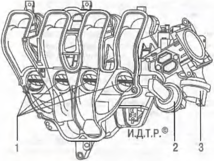
Rice. 5.1. The intake manifold of the 2.0 l Duratec Ti-VCT engine: 1 - dampers for controlling the intake manifold channels; 2 - actuator of the dampers for controlling the intake manifold channels; 3 - swirl damper drive
two solenoid valves 5 and 7 are fixed, which hydraulically control the VCT mechanisms. The solenoid valves, in turn, are controlled by the electronic engine control unit.
The oil supplied to the VCT hydraulic system from the main engine oil line, in addition to the main oil filter of the lubrication system, is cleaned in an additional filter 9 (Fig. 5.3). Additional oil cleaning is required because the solenoid valve bores are very small and contaminant particles as small as 0.2 mm can already lead to failure of the VCT system. At the same time, the filter acts as a safety valve to ensure an uninterrupted supply of oil to the VCT hydraulic system under all circumstances. The filter is non-removable and cannot be replaced.
The solenoid valve VCT, consisting of an electromagnet 1 (Fig. 5.4) and a valve that includes a spool 2 and a spring 7, according to the signals of the electronic engine control unit, supplies oil under pressure from the main line of the lubrication system to the working cavities of the VCT mechanisms or drains oil from these cavities, which leads to the mutual movement of the elements of the mechanisms and, as a result, to a dynamic change in the position of the camshafts.
While the engine is idling, the electronic engine control unit repeatedly activates the electromagnetic valves for short periods of time in order to clean their elements and channels from contaminants that accidentally get into them.
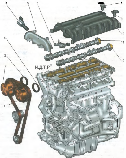
Rice. 5.2. Elements of the variable valve timing system (VCT) of the 1.6 l Duratec Ti-VCT engine: 1 - intake camshaft VCT mechanism; 2 - exhaust camshaft VCT mechanism; 3 - inlet camshaft seal; 4 - an epiploon of a final camshaft; 5 - solenoid valve for adjusting the position of the exhaust camshaft; 6 - support of the VCT system; 7 - solenoid valve for controlling the position of the intake camshaft; 8 - exhaust camshaft position sensor; 9 - intake camshaft position sensor; 10 - cylinder head cover; 11 - setting ring of the exhaust camshaft position sensor; 12 - the driving ring of the intake camshaft position sensor.
When the power supply to the VCT solenoid valves is turned off, the oil supply holes 6 from the main line and drain 8 are completely open and the VCT mechanisms are set to their original position. In this case, the engine runs without changing the valve timing.
Elements of the VCT system (solenoid valves and mechanisms for dynamically changing the position of camshafts) are precision-manufactured components. In this regard, when performing maintenance or repair of the variable valve timing system, only the replacement of the complete system elements is allowed.
Source: Operation, maintenance and repair manual in photographs series "Repair without problems" Third Rome