![1 generation [2009 - 2014]](/uploads/Renault_Sandero_2009-2014_.jpg)

Clutch elements for Logan and Sandero cars:
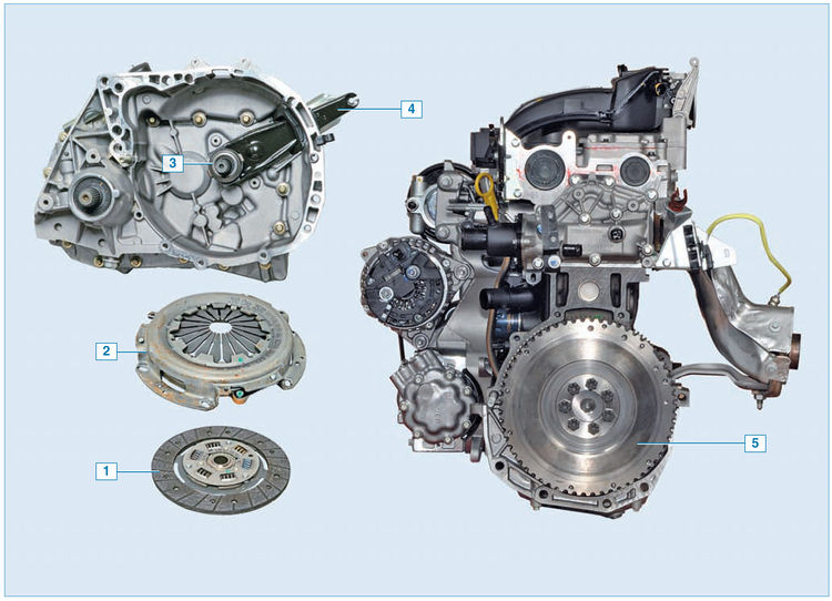
1 - driven disk;
2 - pressure plate with casing assembly ("basket");
3 - clutch release bearing with clutch assembly;
4 - clutch release fork;
5 - flywheel
Clutch - single-disk, dry, with a central diaphragm spring. The mechanism is located in an aluminum crankcase, structurally integrated with the gearbox and attached to the engine block.
“Basket” of the clutch (pressure plate with casing assembly):
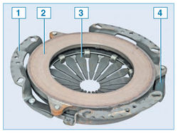
1 - clutch cover;
2 - pressure plate;
3 - diaphragm spring;
4 - connecting plate
The clutch casing is connected by six bolts to the engine flywheel. Three pins are pressed into the flywheel, which, when the clutch is installed, enter the corresponding holes in the casing, centering it. A diaphragm spring is installed in the casing. Stamped from sheet spring steel. In the free state, the diaphragm spring has the form of a truncated cone with radial slots extending from the inner edge of the spring. The slots of the spring form eighteen petals, which are elastic release levers. Due to the elasticity of the levers, the diaphragm spring creates a more even pressure on the clutch pressure plate and contributes to smoother engagement and disengagement of the clutch.
At three points, the casing is connected by elastic steel plates to the pressure (leading) disk. This assembly (also called the "basket" of the clutch) is balanced in the assembly on the stand, therefore it is replaced entirely. Replacing the "basket" is necessary when the annular wear of the petals of the diaphragm spring to a depth of more than 0.8 mm, as well as in the event of a decrease in the effort on the pedals when the clutch is turned off (and, accordingly, an increase in the stroke), which indicates a large wear on the surface of the pressure plate or " draft" of the spring.
Driven clutch disc:
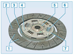
1 - friction lining rivet;
2 - friction linings;
3 - spring plate;
4 - support pin;
5 – disk hub;
6 - damper spring;
7 - damper plate
The driven disk with a spring damper of torsional vibrations is located on the splines of the input shaft of the gearbox between the flywheel and the pressure plate.
Provides an elastic connection between the clutch disc and the input shaft of the gearbox. It dampens torsional vibrations arising from dynamic loads in the transmission and uneven engine operation. Two disc friction linings are riveted on both sides to a spring plate, which, in turn, is riveted to one of the two damper plates. A disk hub is installed between the damper plates. Damper springs are installed in the holes of the hub and damper plates. The damper plates are connected by three support pins. In the disc hub, opposite the support pins, there are cutouts that allow the hub to rotate within certain limits relative to the damper plates, while compressing the damper springs. This allows you to reduce dynamic loads in the transmission when starting the car and when shifting gears.
The outer diameter of the driven disk for a car with a 1.4 liter engine is 180 mm, with a 1.6 liter engine - 200 mm, the thickness of the disk is 7.6 mm. The driven disk is replaced if its axial runout in the area of the friction linings is more than 0.5 mm, oiling, cracking, scuffing or uneven wear of the linings, weakening of the rivet joints, and also if the heads of the rivets are deepened from the surface of the linings by less than 0.2 mm.
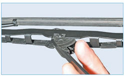
Clutch cable:

1 - front tip of the cable;
2 - front tip of the cable sheath;
3 - rear tip of the cable;
4 - rear tip of the cable sheath;
5 - cable;
6 - rubber support sleeve
Clutch drive on Logan and Sandero cars - cable, backlash-free. The front end of the cable is attached to the clutch release fork, and the rear end is attached to the clutch pedal holder.
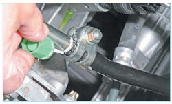
The front tip is threaded, used to adjust the clutch release drive.
The clutch pedal is mounted on an axle in the pedal assembly bracket. Pedal return spring is installed on the same axis.
The fork pivots on a ball joint mounted in the clutch housing. A clutch release bearing is installed between the clutch release fork and the diaphragm spring petals. The bearing sleeve has two hooks with which it is hooked onto the fork legs. A clutch drive scheme has been applied, in which the bearing is constantly pressed against the petals of the diaphragm spring. The bearing moves freely along the guide sleeve pressed into the clutch housing.
Elements of the clutch drive mechanism:
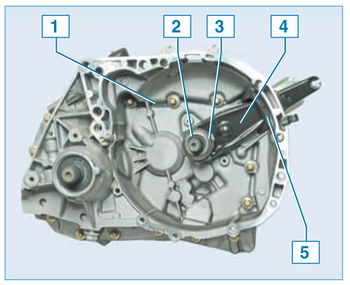
1 - clutch housing;
2 – the directing plug of the bearing of deenergizing of coupling;
3 - clutch release bearing with clutch assembly;
4 - clutch release fork;
5 - dirt cover
Clutch disengagement occurs as follows. When the clutch pedal is depressed, the cable turns the clutch release fork, which moves the bearing along the guide sleeve. The bearing presses on the petals of the diaphragm spring. The spring, deforming, ceases to press the pressure plate against the flywheel, while the pressure plate moves away from the flywheel, as a result of which the engine crankshaft and the gearbox input shaft can rotate independently of each other. When the clutch pedal is released, the bearing returns to its original position, while the diaphragm spring again begins to press on the pressure plate, which, in turn, presses the driven disc against the flywheel - as a result, the transmission of torque resumes.
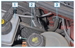
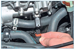
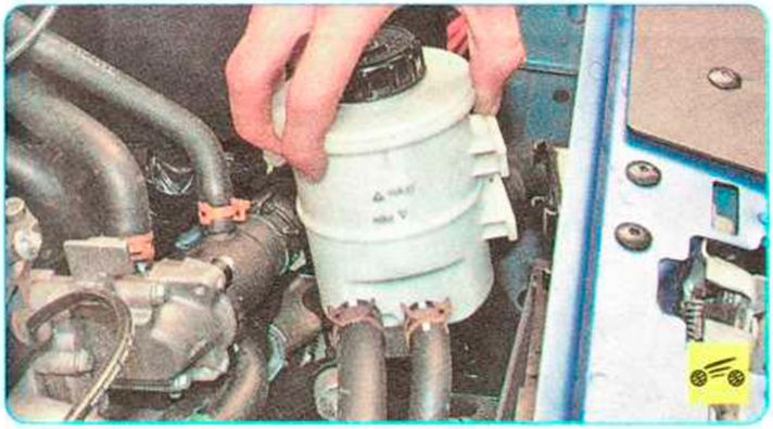
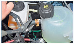
Elements of the hydraulic clutch of the car Sandero Stepway :
1 - reservoir of the main brake cylinder and clutch cylinder;
2 - a tube for supplying fluid to the clutch master cylinder;
3 - clutch master cylinder
The Sandero Stepway car uses a hydraulic clutch release drive.
The drive for disengaging the clutch mechanism consists of a clutch pedal, a clutch master cylinder, a release bearing combined with a working cylinder, and connecting lines. The drive uses brake fluid, poured into a supply tank, which is located on the main brake cylinder and is used simultaneously to power the brake system and drive the clutch mechanism off.
The clutch master cylinder is mounted on the bulkhead, and the cylinder rod is connected to the pedal.
A filler tube leads from the reservoir on the brake master cylinder to the clutch master cylinder. When you press the pedal, the rod moves, creating fluid pressure in the working line, which acts on the clutch slave cylinder. The slave cylinder is mounted inside the clutch housing and aligned with the release bearing. When pressure is applied, the slave cylinder piston acts on the bearing, moving it forward and thus disengaging the clutch. The helical spring constantly keeps the release bearing pressed against the clutch basket diaphragm spring. The diaphragm spring returns the bearing to its original position after the pressure in the line is relieved.
The release bearing contains a "lifetime" supply of grease and is maintenance free. Because the bearing and diaphragm spring are in constant contact, there is no play in the clutch mechanism, so no adjustment is required.
At the junction of the clutch slave cylinder with the fluid supply line, which is a steel tube, there is a bleed valve for the hydraulic clutch actuator.
Source: http://wiki.zr.ru/182-3_%D0%A0%D0%B5%D0%BC%D0%BE%D0%BD%D1%82_Stepway