Elements of the brake system of a car with an anti-lock braking system (ABS):
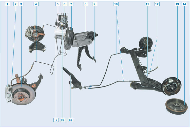
1 - floating bracket;
2 – front wheel brake hose;
3 – a disk of the brake mechanism of a forward wheel;
4 – a tube of the brake mechanism of a forward wheel;
5 – hydraulic drive reservoir;
6 - block ABS;
7 - vacuum brake booster;
8 - pedal assembly;
9 – brake pedal;
10 - rear parking brake cable;
11 – a tube of the brake mechanism of a back wheel;
12 – a hose of the brake mechanism of a back wheel;
13 - brake mechanism of the rear wheel;
14 – rear wheel brake drum;
15 – parking brake lever;
16 - sensor for signaling an insufficient level of brake fluid;
17 - the main brake cylinder
The working brake system is hydraulic, dual-circuit with diagonal separation of circuits. In normal mode (when the system is working), both circuits work. In case of failure (depressurization) of one of the circuits, the second one provides braking of the car, although with less efficiency.
The working brake system includes wheel brakes, pedal assembly, vacuum booster, brake master cylinder, hydraulic reservoir, rear wheel brake pressure regulator (only on vehicles without ABS), ABS unit, as well as connecting pipes and hoses.
Pedal assembly with vacuum booster and brake master cylinder:
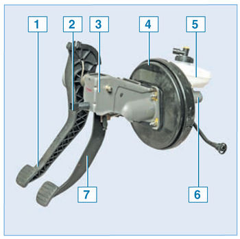
1 - clutch pedal;
2 – the switch of signals of braking;
3 – pedal assembly bracket;
4 - vacuum brake booster;
5 - a reservoir of the hydraulic drive of the system;
6 - the main brake cylinder;
7 - brake pedal
Brake pedal - suspension type. A brake light switch is installed in the pedal assembly bracket in front of the brake pedal - its contacts close when the pedal is pressed.
The vacuum brake booster is located in the engine compartment between the pedal pusher and the main brake cylinder and is fastened with four nuts through the bulkhead to the pedal bracket. The vacuum booster is non-separable, in case of failure it is replaced.
The main brake cylinder is attached to the vacuum booster housing with two studs. On top of the cylinder there is a reservoir of the hydraulic drive of the brake system, in which there is a supply of fluid. The tank body is marked with maximum and minimum liquid levels, and a sensor is installed in the tank lid, which, when the liquid level drops below the MIN mark, turns on a signaling device in the instrument cluster.
When the brake pedal is pressed, the pistons of the master cylinder move, creating pressure in the hydraulic drive, which is supplied through pipes and hoses to the working cylinders of the wheel brake mechanisms.
Location of the pressure regulator in the hydraulic drive of the brake mechanisms of the rear wheels:
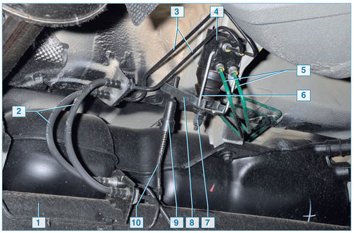
1 - rear suspension beam;
2 – hoses of brake mechanisms of back wheels;
3 – tubes of brake mechanisms of back wheels;
4 - pressure regulator;
5 - tubes for supplying brake fluid to the pressure regulator;
6 - regulator bracket;
7 - adjusting nut of the regulator stud;
8 – pressure lever;
9 - thrust adjusting sleeve;
10 - thrust
On a vehicle without ABS, fluid for the rear wheel brakes is supplied through a pressure regulator located on the bottom of the body, between the rear suspension beam and the spare wheel punch.
With an increase in the load on the rear axle of the car, the regulator rod connected to the rear suspension beam is loaded, transferring force through the pressure lever to the pin and then to the two regulator pistons.
Rear wheel brake pressure regulator parts:
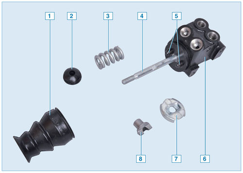
1 – mud-protective cover;
2 - support sleeve;
3 - spring;
4 - pressure regulator pin;
5 - pressure regulator pistons;
6 - pressure regulator housing;
7 - thrust washer;
8 - guide sleeve
When the brake pedal is depressed, fluid pressure tends to push the pistons out of the regulator body, which is prevented (through a spring) by the force from the regulator rod. When the system comes into balance, the valve located in the regulator shuts off the fluid supply to the wheel cylinders of the rear wheel brake mechanisms, preventing further growth of the braking force on the rear axle and preventing the rear wheels from locking ahead of the front wheels.
Rear wheel brake pressure regulator with levers:
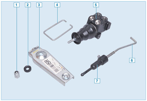
1 - adjusting nut;
2 - plastic sleeve;
3 – pressure lever;
4 - regulator bracket;
5 - pressure regulator;
6 - draft regulator;
7 – thrust adjusting sleeve
With an increase in the load on the rear axle, when the grip of the rear wheels with the road improves, the regulator provides more fluid pressure in the wheel cylinders of the brake mechanisms of the rear wheels, and vice versa, with a decrease in the load on the rear axle (for example, when the car “pecks” during a sharp braking) the pressure decreases
ABS block:
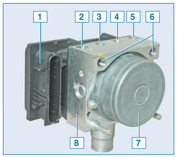
1 - control unit;
2 - hole for connecting the tube of the brake mechanism of the front right wheel;
3 - hole for connecting the tube of the brake mechanism of the rear left wheel;
4 - hole for connecting the tube of the brake mechanism of the rear right wheel;
5 - hole for connecting the tube of the brake mechanism of the front left wheel;
6 – an opening for connection of a tube of the main brake cylinder;
7 - pump;
8 - hydraulic block
Some cars are equipped with an anti-lock braking system (ABS), which provides more efficient braking of the car by reducing fluid pressure in the brake mechanisms of the wheels at the time of their blocking. Prevents skidding and maintains controllability.
On a car with ABS, the fluid from the master brake cylinder enters the ABS unit, and from there it is supplied to the brake mechanisms of all wheels.
The ABS block, mounted in the engine compartment on the right side member, near the bulkhead, consists of a hydraulic unit, a modulator, a pump and a control unit.
Location of the front wheel speed sensor in the hub assembly:
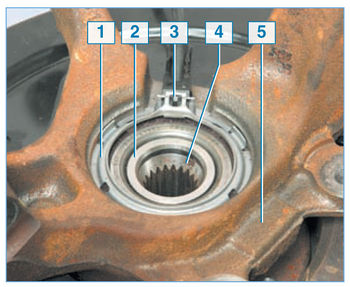
1 - adjusting ring of the speed sensor;
2 – an internal ring of the bearing of a nave;
3 – wheel speed sensor;
4 - wheel hub;
5 - steering knuckle
ABS operates depending on the signals from the wheel speed sensors of the inductive type. The front wheel speed sensor is located in the wheel hub assembly - it is inserted into the groove of a special sensor mounting ring, sandwiched between the end surface of the outer ring of the hub bearing and the shoulder of the steering knuckle hole for the bearing.
Elements of the front wheel speed sensor:
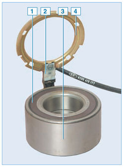
1 - protective washer of the bearing;
2 – speed sensor;
3 - hub bearing;
4 - adjusting ring of the speed sensor
The driving disk of the speed sensor of the front wheel is the protective washer of the hub bearing, located on one of the two end surfaces of the bearing. This dark color puck is made of magnetic material. On the other end surface of the bearing there is an ordinary light-colored protective washer made of tin.
Arrangement of the driving disk of the sensor of speed of rotation of a back wheel:
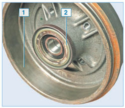
1 – brake drum;
2 – speed sensor setting disk
The rear wheel rotation speed sensor is fixed on the brake shield, and the sensor setting disk is a ring made of magnetic material pressed onto the shoulder of the brake drum.
Front 1 and rear 2 wheel speed sensors
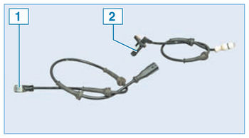
When the vehicle is braked, the ABS control unit detects the start of a wheel lock and opens the corresponding modulator solenoid valve to release the pressure of the working fluid in the channel. The valve opens and closes several times per second, so you can verify that the ABS is working by the slight vibration of the brake pedal at the time of braking. In the event of a malfunction in the ABS, the brake system remains operational, but the wheels may lock. In this case, the corresponding fault code is written to the memory of the control unit, which is read using special equipment in the service center.
The brake mechanism of a forward wheel assy:
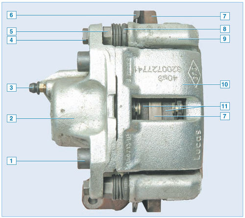
1 - screw securing the cylinder body to the caliper;
2 – the case of the wheel cylinder;
3 - bleed valve for hydraulic brakes;
4 – a bolt of fastening of a bracket to a directing finger;
5 - guide pin;
6 - shield of the brake mechanism;
7 – a disk of the brake mechanism;
8 – a cover of a directing finger;
9 - guide block;
10 - support;
11 - brake pads
The brake mechanism of the front wheel is disc, with a floating caliper, which includes a caliper and a single-piston wheel cylinder, held together by two screws. The brake mechanisms of the front wheels of cars with engines with a working volume of 1.4 liters and a volume of 1.6 liters are the same. Some cars are equipped with brake mechanisms with ventilated discs.
Elements of the brake mechanism of the front wheel:
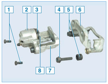
1 – a bolt of fastening of a bracket to a directing finger;
2 – the case of the wheel cylinder;
3 – a protective cover of the piston;
4 - guide pin;
5 - protective cover of the guide pin;
6 - guide pads;
7 - support;
8 - piston
The brake pad guide is attached to the steering knuckle with two bolts, and the bracket is attached with two bolts to the guide pins installed in the holes of the guide pad. Protective rubber covers are installed on the fingers. The holes for the pins of the guide pads are filled with grease. The brake pads are pressed against the grooves of the guide by springs.
When braking, the fluid pressure in the hydraulic drive of the brake mechanism increases and the piston, moving out of the wheel cylinder, presses the inner brake pad against the disc. Then the bracket (due to the movement of the guide pins in the holes of the guide pads) moves relative to the disc, pressing the outer brake pad against it. A piston with a sealing rubber ring of rectangular section is installed in the cylinder body attached to the caliper. Due to the elasticity of this ring, a constant optimal gap is maintained between the disc and the brake pads.
Rear wheel brake with drum removed:
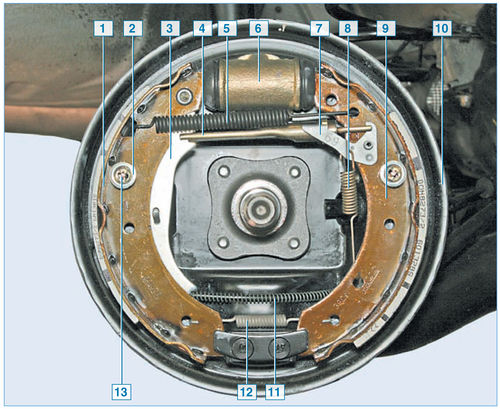
1 - rear brake shoe;
2 – spring cup;
3 – the lever of a drive of a parking brake;
4 - spacer bar;
5 - upper coupling spring;
6 – wheel cylinder;
7 – regulator lever;
8 - regulator spring;
9 - front block;
10 - shield;
11 – parking brake cable;
12 - lower coupling spring;
13 - support post
The brake mechanism of the rear wheel is drum, with a two-piston wheel cylinder and two brake shoes, with automatic adjustment of the gap between the shoes and the drum.
The brake mechanisms of the rear wheels of cars with engines with a working volume of 1.4 liters and a volume of 1.6 liters are the same.
The brake drum is integral with the rear wheel hub.
The automatic clearance adjustment mechanism consists of a composite pad spacer bar, a regulator lever and its spring. The automatic adjustment mechanism starts to work when the gap between the shoes and the brake drum increases.
Elements of the brake mechanism of the rear wheel:
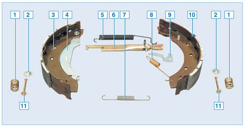
1 - clamping spring pads;
2 – spring cup;
3 - rear block;
4 – the lever of a drive of a parking brake;
5 - upper coupling spring;
6 - spacer bar;
7 - lower coupling spring;
8 - regulator spring;
9 – regulator lever;
10 - front block;
11 - support post
When the brake pedal is pressed, under the action of the pistons of the wheel cylinder, the pads begin to diverge and press against the drum, while the protrusion of the regulator lever moves along the cavity between the teeth of the ratchet nut. With a certain amount of pad wear and the brake pedal depressed, the adjuster lever has enough travel to turn the ratchet nut one tooth, thereby increasing the length of the spacer bar and at the same time reducing the gap between the pads and the drum. Thus, the gradual lengthening of the spacer bar automatically maintains the clearance between the brake drum and the shoes.
The wheel cylinders of the brake mechanisms of the rear wheels are the same. The front pads of the brake mechanisms of the rear wheels are the same, while the rear ones are different - they are mirror-symmetrically installed non-removable levers of the parking brake drive.
Elements of the mechanism for automatic adjustment of the gap between the shoes and the drum:
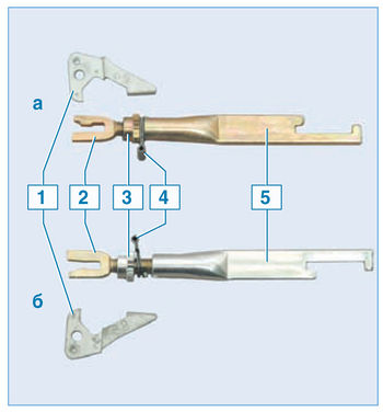
a - the brake mechanism of the right wheel;
b - the brake mechanism of the left wheel;
1 – regulator lever;
2 - threaded tip of the spacer bar;
3 - ratchet nut;
4 - spring stopper;
5 - spacer bar
The spacer bar and the ratchet nut of the brake mechanism of the left wheel are silver (the ratchet nut and the end of the spacer bar have a right-hand thread), and the right wheel is golden (the ratchet nut and the end of the spacer bar have a left-hand thread). The levers of the regulators of the brake mechanisms of the left and right wheels are mirror-symmetrical. The right lever is marked "69" and the left - "68"
Elements of the parking brake:
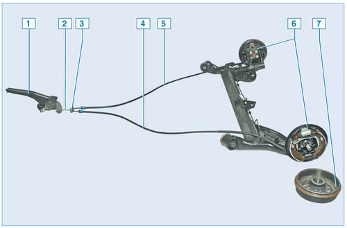
1 - lever;
2 - front cable;
3 – cable equalizer;
4 - left rear cable;
5 - right rear cable;
6 – brake mechanism of the rear wheel;
7 - drum
Parking brake drive - manual, mechanical, cable, on the rear wheels. It consists of a lever, a front cable with an adjusting nut on its tip, an equalizer, two rear cables and levers in the rear wheel brakes.
The parking brake lever, fixed between the front seats on the floor tunnel, is connected to the front cable. An equalizer is attached to the rear tip of the front cable, into the holes of which the front tips of the rear cables are inserted. The rear ends of the cables are connected to the parking brake levers attached to the rear shoes.
During operation (until the rear brake pads are completely worn out), adjustment of the parking brake drive is not required, since the lengthening of the brake mechanism spacer bar compensates for the wear of the pads. The parking brake actuator only needs to be adjusted if the brake pads, cables or parking brake lever have been replaced.
Source: http://wiki.zr.ru/222-2_%D0%A0%D0%B5%D0%BC%D0%BE%D0%BD%D1%82_Stepway

![1 generation [2009 - 2014]](/uploads/Renault_Sandero_2009-2014_.jpg)
