![CM [2006 - 2010]](/uploads/Hyundai_Santa_Fe_2006-2010_.jpg)
![DM [2012 - 2016]](/uploads/Hyundai_Santa_Fe_2012_-_3.jpg)

- The engine is four-cylinder, in-line, transversely located, with an overhead arrangement of two camshafts 1 and 2 (Fig. 5.15), has four valves for each cylinder.
- The cylinder head 9 (Fig. 5.16) is made of aluminum alloy according to the transverse cylinder purge pattern (inlet and outlet channels are located on opposite sides of the head). Seats and valve guides are pressed into the heads. The intake and exhaust valves have one spring each, fixed through the plate with two crackers.
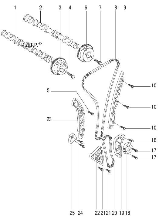
- Rice. 5.15. The drive of the gas distribution mechanism and the balance shafts of the engine with a volume of 2.4 liters: 1 - exhaust camshaft; 2 – a camshaft of inlet valves; 3 – an asterisk of a camshaft of final valves; 4 – a bolt of fastening of an asterisk of a camshaft; 5 - bolt for fastening the shoe of the tensioner of the timing chain; 6 - solenoid valve CVVT; 7 – a bolt of fastening of the electromagnetic valve CVVT; 8 – a chain of a drive of the gas-distributing mechanism; 9 - guide shoe of the timing chain drive; 10 – a bolt of fastening of a directing shoe of a chain of a drive of the gas-distributing mechanism; 11, 13, 14 - bolts for fastening the cover of the timing chain drive; 12 – an epiploon of a cranked shaft; 15 – a cover of a chain of a drive of the gas-distributing mechanism; 16 – a bolt of fastening of a shoe of a tensioner of a chain of a drive of balancing shafts; 17 – a bolt of fastening of a tensioner of a chain of a drive of balancing shafts; 18 - chain tensioner drive balancer shafts; 19 - shoe drive chain balancing shafts; 20 - balancer shaft drive chain; 21 - bolts for fastening the guide shoe of the balancer shaft drive chain; 22 - shoe drive chain balancing shafts; 23 – a shoe of a chain of a drive of the gas-distributing mechanism; 24 - bolts for fastening the timing chain tensioner; 25 - timing chain tensioner 21 - bolts for fastening the guide shoe of the balancer shaft drive chain; 22 - shoe drive chain balancing shafts; 23 – a shoe of a chain of a drive of the gas-distributing mechanism; 24 - bolts for fastening the timing chain tensioner; 25 - timing chain tensioner 21 - bolts for fastening the guide shoe of the balancer shaft drive chain; 22 - shoe drive chain balancing shafts; 23 – a shoe of a chain of a drive of the gas-distributing mechanism; 24 - bolts for fastening the timing chain tensioner; 25 - timing chain tensioner
- The camshafts are installed in the bed of bearings, made in the body of the head, and secured with covers. The camshafts are driven by a chain from the camshaft sprocket.
- The cylinder block is a single casting that forms the cylinders, the cooling jacket, the upper part of the crankcase and five crankshaft bearings made in the form of crankcase partitions. The block is made of special ductile iron with cylinders bored directly in the body of the block. Main bearing caps machined complete with block are not interchangeable. On the cylinder block, special lugs, flanges and holes for fastening parts, assemblies and assemblies, as well as channels of the main oil line are made. From below, the cylinder block is closed by an oil sump.
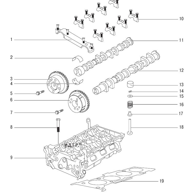
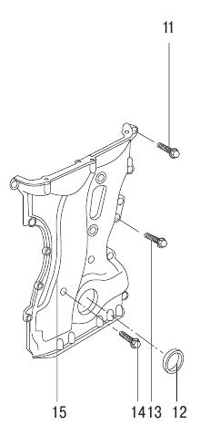
- Rice. 5.16. The gas distribution mechanism of the engine with a volume of 2.4 liters: 1 - the front cover of the camshafts; 2, 4 - camshaft liners; 3 – an asterisk of a camshaft of final valves; 5 – a bolt of fastening of an asterisk of a camshaft of final valves; 6 - solenoid valve CVVT; 7 – a bolt of fastening of the electromagnetic valve CVVT; 8 – a bolt of fastening of a head of the block of cylinders; 9 – a head of the block of cylinders; 10 - camshaft covers; 11 - exhaust camshaft; 12 - intake camshaft; 13 - valve lifter; 14 – crackers of a plate of the valve; 15 - valve plate; 16 - valve spring; 17 - valve guide; 18 - valve; 19 – a lining of a head of the block of cylinders
- The crankshaft rotates in main bearings with thin-walled steel liners coated with an anti-friction layer. The axial movement of the crankshaft is limited by two half rings. The cast iron flywheel is mounted on the rear end of the crankshaft and bolted. A gear rim is pressed onto the flywheel for starting the engine with a starter. In addition, a ring gear is made on the flywheel, which plays the role of a master ring for the crankshaft position sensor of the engine control system. On cars with an automatic transmission, instead of a flywheel, a torque converter drive disc is installed.
- The pistons are made of aluminum alloy. On the cylindrical surface of the piston head, annular grooves are made for two compression rings, as well as an oil scraper ring.
- The piston pins are installed in the piston bosses with a gap and are pressed with an interference fit into the upper heads of the connecting rods, which are connected with their lower heads to the connecting rod journals of the crankshaft through thin-walled liners, the design of which is similar to that of the main bearings.
- Connecting rods are steel, forged, with an I-section rod.
- Combined lubrication system (for details, see "Lubrication system").
- The closed crankcase ventilation system does not communicate directly with the atmosphere, therefore, simultaneously with the exhaust of gases, a vacuum is formed in the crankcase under all engine operating modes, which increases the reliability of various engine seals and reduces the emission of toxic substances into the atmosphere.
- The cooling system is sealed, with an expansion tank, consists of a cooling jacket, made in casting and surrounding the cylinders in the block, combustion chambers and gas channels in the cylinder head. Forced circulation of the coolant is provided by a centrifugal water pump. To maintain the normal operating temperature of the liquid in the cooling system, a thermostat is installed that covers a large circle of the system when the engine is cold and the coolant temperature is low.
- The power system consists of an electric fuel pump installed in the fuel tank, a throttle assembly, a fine fuel filter installed in the fuel pump module, a fuel pressure regulator, injectors and fuel lines, and also includes an air filter.
- The power unit (engine with clutch, gearbox, final drive and transfer case) is mounted on four supports with elastic rubber elements: two lateral (right and left), which take the bulk of the power unit, as well as rear and front, compensating the torque from the transmission and the loads that occur when starting the car from a standstill, accelerating and braking.
- Balance shafts are installed in the cylinder block and are designed to dampen inertia forces. The shafts are parallel to each other and rotate in opposite directions at a speed twice that of the crankshaft. To better balance the engine, the balance shafts are located in the cylinder block above the crankshaft.
- Source: Hyundai Santa Fe Owner's Manual, Third Rome Publishing House
The article is missing:
- The article does not match the car
The article lacks:
- Статья не соответствует машине

Removing and installing the front seat Hyundai Santa Fe CM 2006-2012
30 minutes - 1 hour
[[ article.getBookmarkIcon() ]]
Instrument
Checking the level, topping up and changing the oil in the rear wheel drive gearbox Hyundai Santa Fe
[[ article.getBookmarkIcon() ]]
Instrument

Replacing bulbs in the headlights Hyundai Santa Fe CM 2006-2012
5 - 30 minutes
[[ article.getBookmarkIcon() ]]
Instrument
Removing and installing rear bumper Hyundai Santa Fe
1 to 3 hours
[[ article.getBookmarkIcon() ]]
Instrument
Replacement of pipelines of the brake system Hyundai Santa Fe
[[ article.getBookmarkIcon() ]]
Instrument
Checking the technical condition of the front suspension parts on a Hyundai Santa Fe car
[[ article.getBookmarkIcon() ]]
No tools