![1 generation [2009 - 2014]](/uploads/Renault_Sandero_2009-2014_.jpg)

If the crankshaft position sensor or its circuits are faulty, the engine will not start or run.
With the ignition off, disconnect the wiring harness connector from the crankshaft position sensor.
We connect the tester probes to terminal “2” of the sensor wiring harness block and to the “mass” of the engine. With the ignition on and the crankshaft stationary...
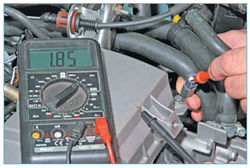
... the tester should detect a voltage of about 2.0 V.
A similar voltage should be between terminal “1” of the sensor wiring harness block and engine ground. If the voltage values do not correspond to the norm, we disconnect (with the ignition off) the wiring harness block from the computer. We check the serviceability of the circuits (open circuit and short to ground) between terminal "2" of the sensor wiring harness block and terminal "24" of the ECU wiring harness block, as well as between terminal "1" of the sensor wiring harness block and terminal "54" of the wiring harness block ECU. If the voltage values \u200b\u200band serviceable circuits do not match, the computer is faulty.
To check the resistance of the sensor winding ...
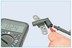
... we connect the tester probes to the sensor terminals (for clarity, it is shown on the removed sensor).
The winding resistance of a good sensor should be 200 - 270 ohms.
To further check the sensor, remove it and connect the tester probes to the sensor terminals.
We switch the tester to the AC voltage measurement mode ...

... and several times we bring a steel rod to the end of the sensor
. If the crankshaft position sensor is working, the device should detect power surges.
Source: http://wiki.zr.ru/72-3_%D0%94%D0%B8%D0%B0%D0%B3%D0%BD%D0%BE%D1%81%D1%82%D0% B8%D0%BA%D0%B0_Stepway