![1 generation [2003 - 2007]](/uploads/Mitsubishi_Outlander_I_2003_-_2008_.jpg)
![3 generation [2012 - 2014]](/uploads/3.png)
![XL [2005 - 2012]](/uploads/4d137205da66f_.jpg)

Tools:
- screw jack
- balloon wrench
- Adjustable support (or lifting device)
- Screwdriver flat medium
- Phillips screwdriver, medium
- 6 mm hex key
- 8mm hex wrench
- Ratchet wrench
- Extension (with cardan)
- Head 10 mm
- Head 12 mm
- Socket 14 mm (produced before 06.2008)
- Head 17 mm
- Straight ring wrench 17 mm
- torque wrench
- Marker
- Hex wrench for fixing the tensioner (or pin)
- Hexagonal special key for fixing the tensioning mechanism (or pin d=2 mm)
- Crankshaft pulley fixing tool (fork holder MB990767 and special bolts and MD998719)
- Knife (release from 07.2008)
- Collar for end nozzle
- Nozzle on the collar 22 mm
- Wheel chock (shoe)
- Bench vice
- Calipers
Parts and consumables:
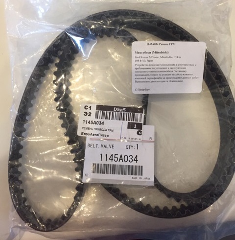
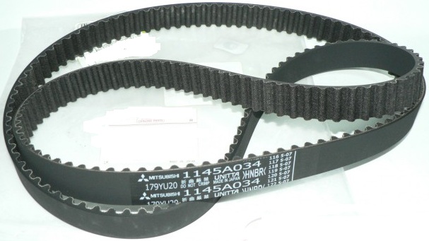
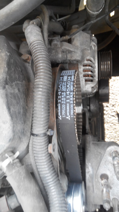
- Timing belt 1145A034
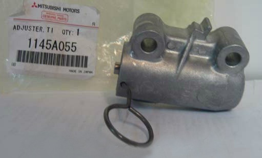
- Timing belt tensioner 1145A055
- Timing belt tensioner 1145A042
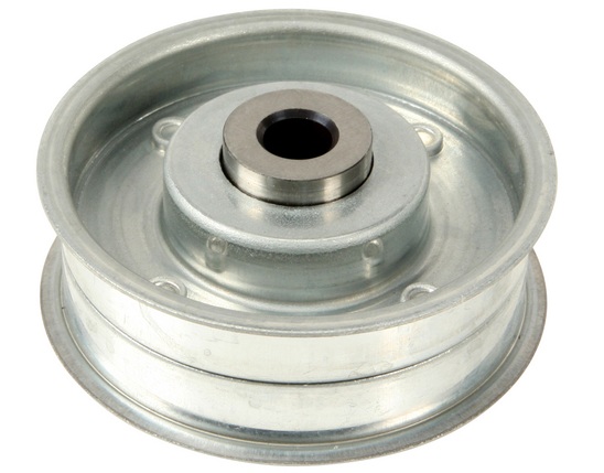
- Timing Belt Intermediate Roller 1145A026
- Accessory drive belt 1340A132
- Power steering pump drive belt 4451A083 (produced before 06.2008, if required)
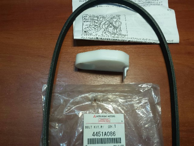
- Power steering pump drive belt (4451A083) with belt installer 4451A086 (from 07.2008, if required)
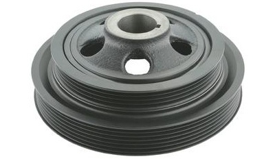
- Crankshaft pulley 1104A044 (if required)
- Wooden block (if necessary)
Notes:
According to the manufacturer's recommendation, the Outlander HL timing belt should be replaced after 90 thousand kilometers or 6 years of operation (whichever comes first). Also replace the belt if, upon inspection, you find:
- traces of oil on any surface of the belt;
- signs of wear of the toothed surface, cracks, undercuts, folds and delamination of the fabric from the rubber;
- cracks, folds, depressions or bulges on the outer surface of the belt;
- fraying of the cord threads or delamination on the end surfaces of the belt.
A belt with traces of engine oil on any of its surfaces must be replaced, as oil quickly destroys rubber. The cause of oil getting on the belt (usually this is a violation of the tightness of the crankshaft and camshaft oil seals) must be eliminated immediately.
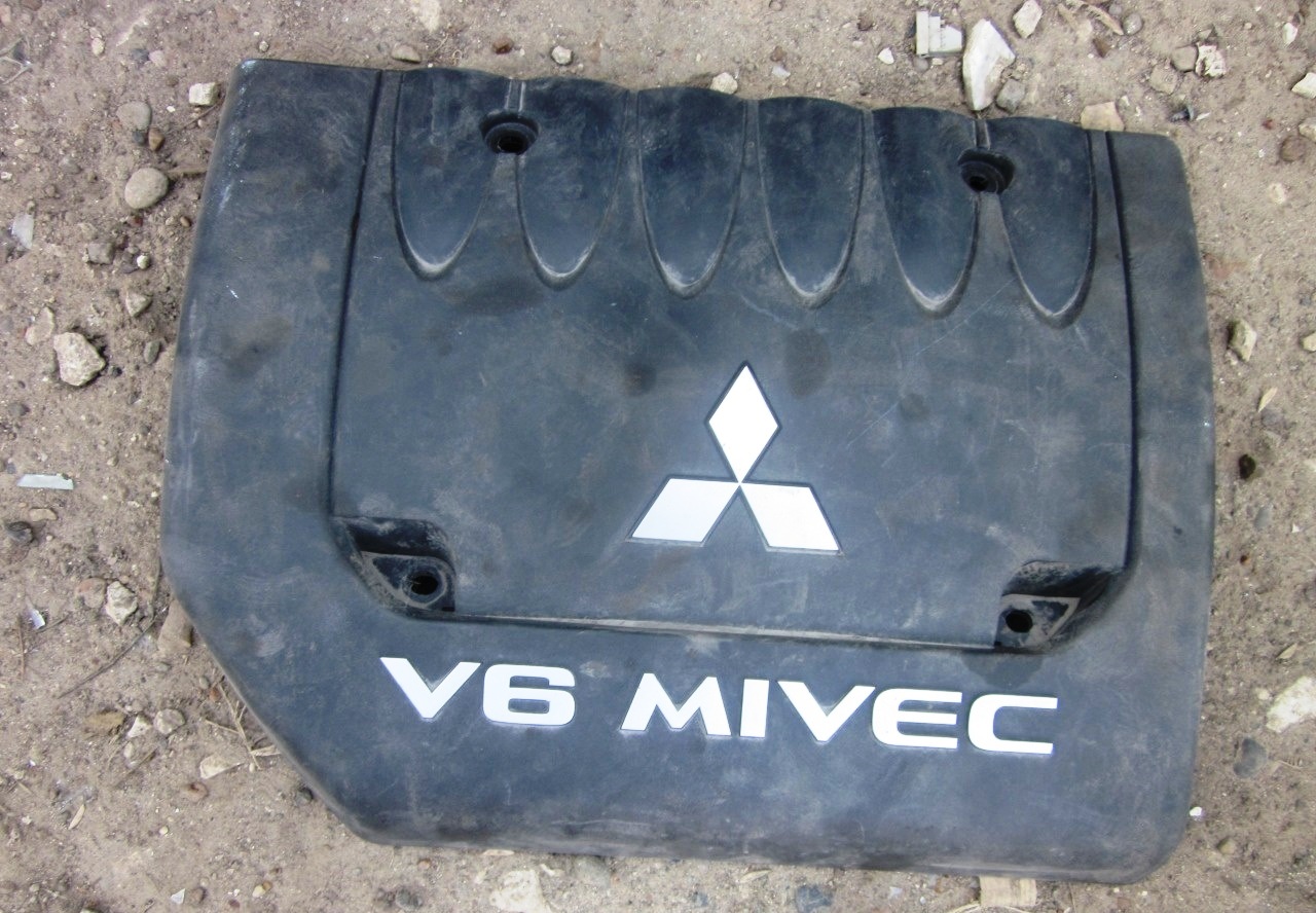
1. Remove the decorative engine cover as described here .
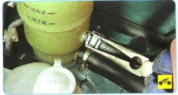
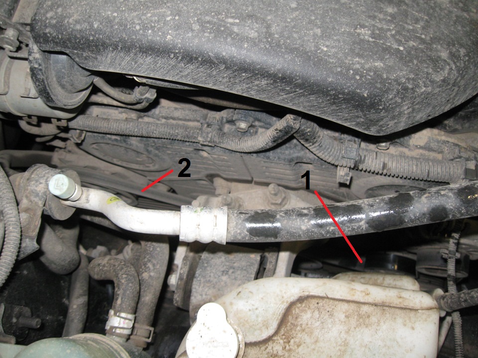
2. Remove the accessory drive belt 1 and the power steering pump 2 as described here .
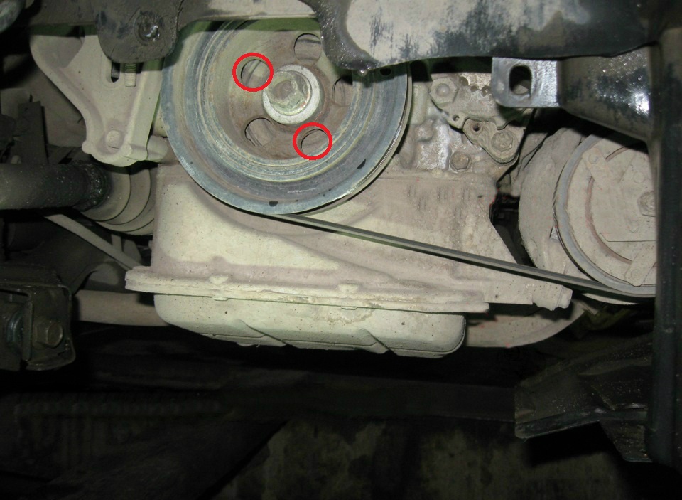
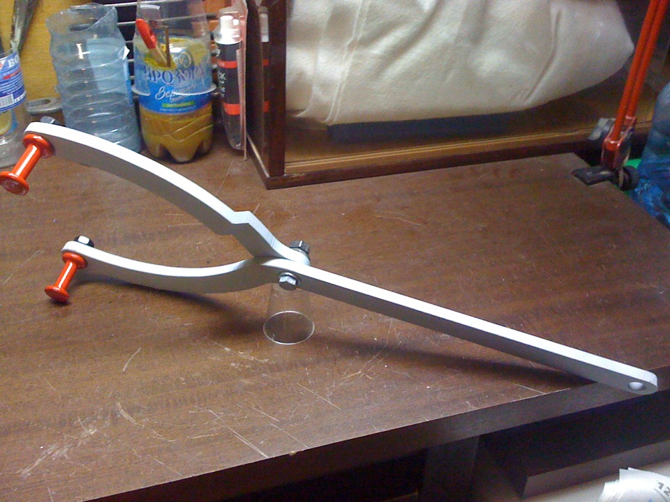
3. Fix the Mitsubishi Outlander HL crankshaft pulley from turning with a special tool (fork holder and special bolts, kn, respectively MB990767 and MD998719).
Note:
To avoid damage to the crankshaft pulley damper, use only the specified special tools for removal.
Attach the special tool securely so that it does not move.
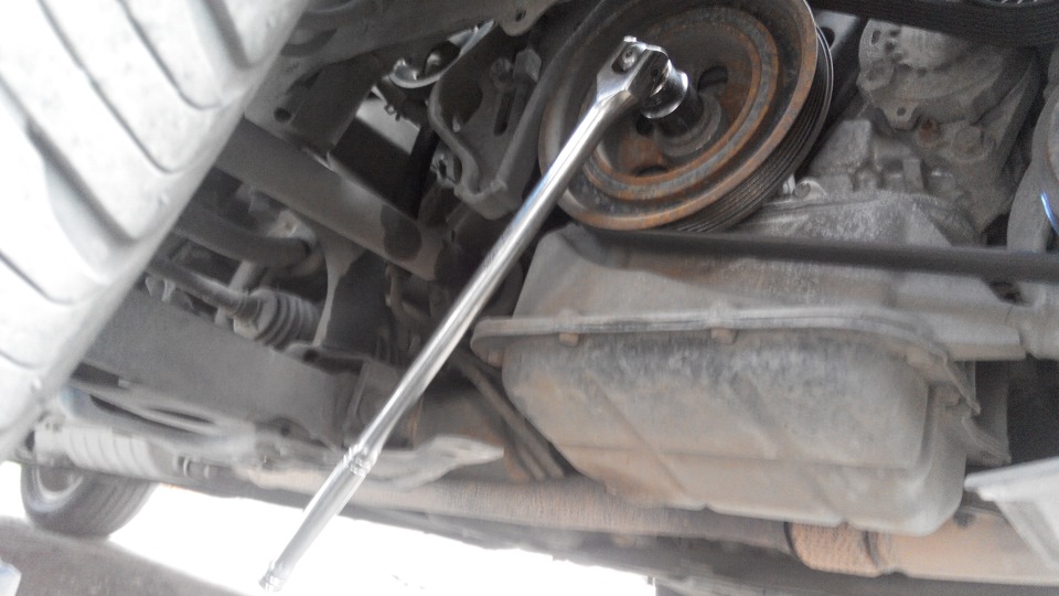
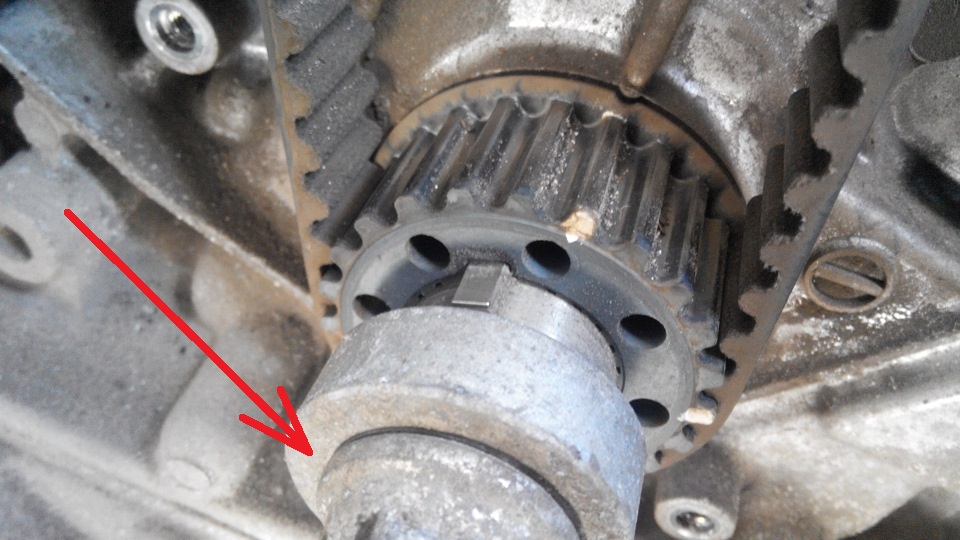
4. Using a 22 mm socket wrench, unscrew the central bolt securing the crankshaft pulley and remove the bolt with washer.
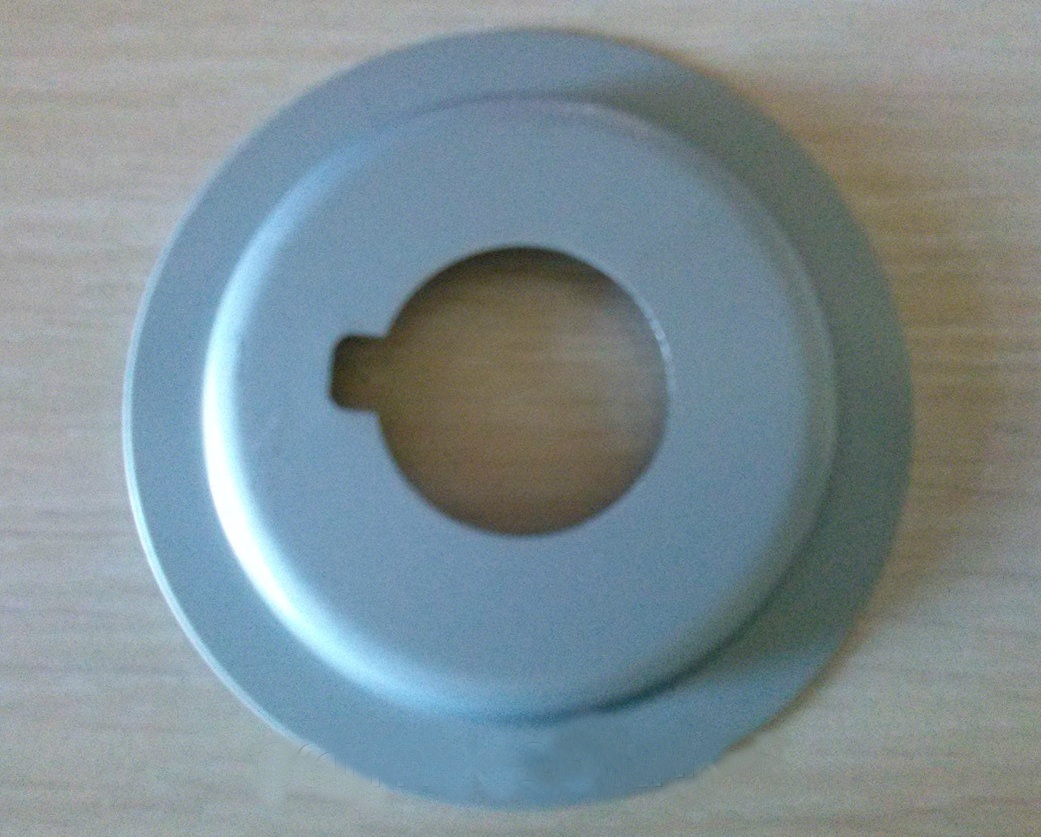
5. Remove the crankshaft pulley and front mudguard.
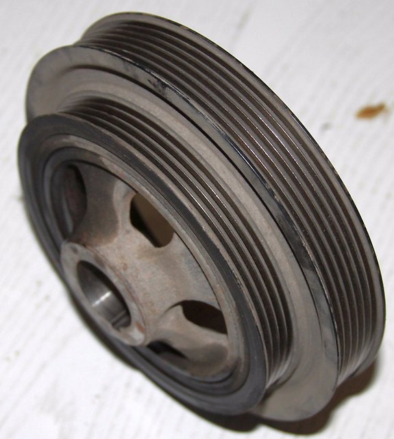
Note:
If the damper is damaged, the crankshaft pulley must be replaced.
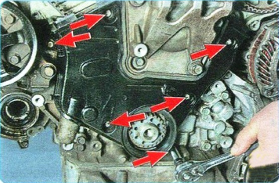
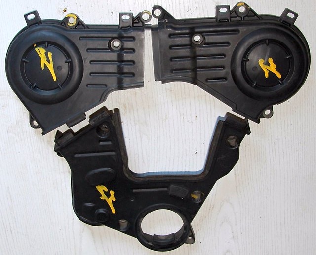
6. Remove the two upper parts of the timing belt cover as described here (points 5-6), and also unscrew the six bolts securing the lower part of the cover and remove it.
7. Remove the right engine mount as described in this article .
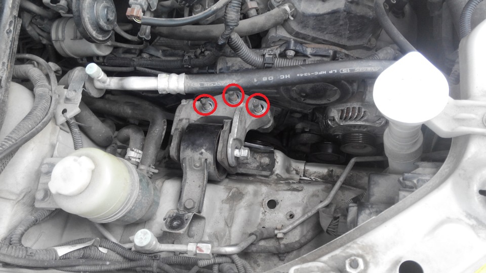
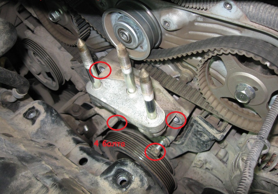
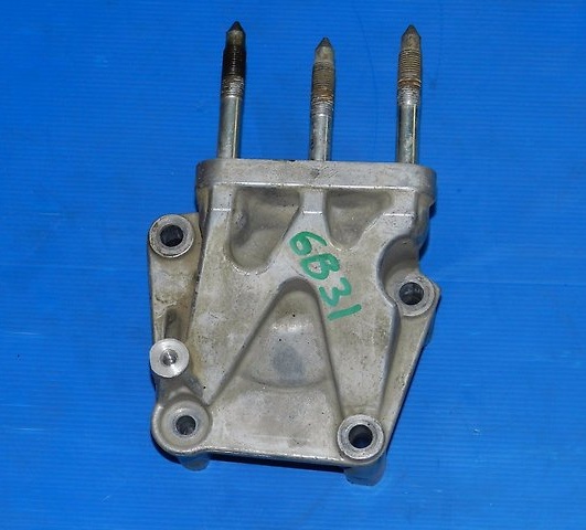
8. Then turn away four bolts of fastening of an arm of the right support of the engine and remove it.
9. Screw the pulley mounting bolt into the crankshaft shank and set the piston of the 1st cylinder to the TDC position of the compression stroke, as described here (points 7-8).
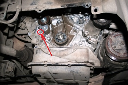
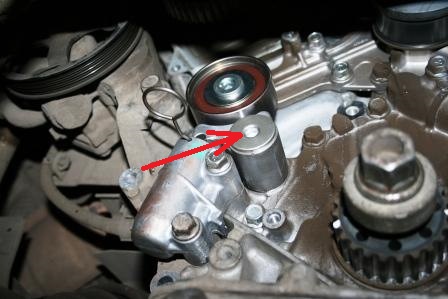
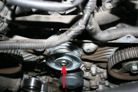
10. To loosen the belt, unscrew the belt tensioner mounting bolt and remove it from the hole in the tensioner housing.
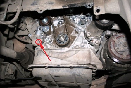
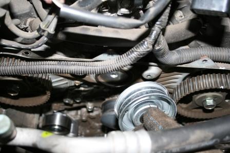
11. After that, loosen the lower mounting bolt and move the tensioner to the left. In this case, the tension roller will go down and the tension of the timing belt will loosen.
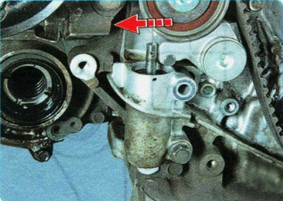
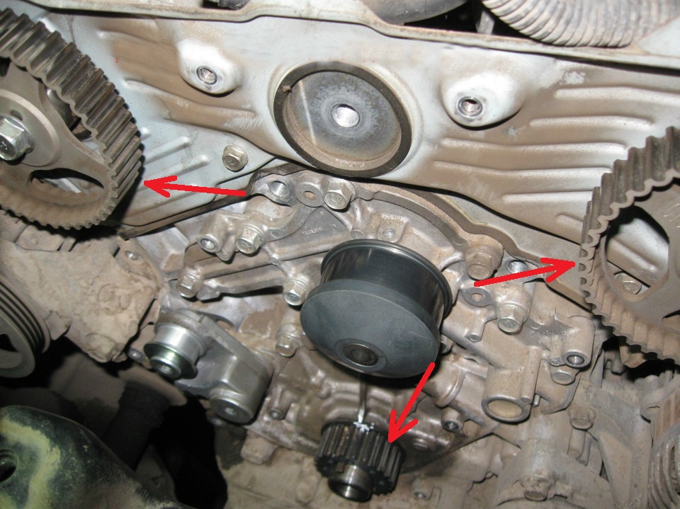
12. Remove the belt from the crankshaft pulley, from the tension and intermediate rollers, as well as from the camshaft pulleys and the water pump.
Note:
After removing the timing belt, it is forbidden to turn the crankshaft and camshafts, as the pistons can damage the valves.
If during repair work the timing belt is removed not for replacement, then mark with an arrow the direction of movement of the belt when the engine is running.
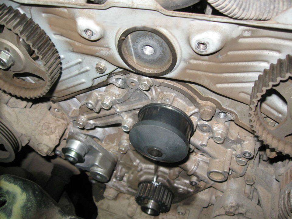
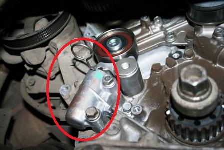
13. To remove the tensioner, finally unscrew and remove the lower bolt (see paragraph 11) of the fastening and remove the tensioner.
14. Examine gear pulleys of a cranked shaft and camshafts. Burrs, nicks, chipping of the working surface of the teeth are not allowed.
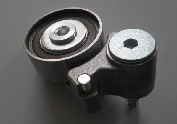
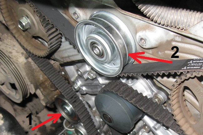
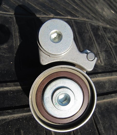
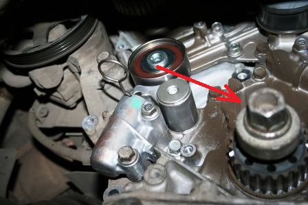
15. Check up tension 1 and intermediate 2 rollers on absence of mechanical damages and ease of rotation. The rollers should rotate silently, without jamming, evenly. There must be no axial and radial play.
Note:
Replace defective parts if necessary.
16. With a hex wrench, unscrew the screw securing the axis of the tension roller lever and remove the roller assembly with the lever.
17. Turn out the screw of fastening of an intermediate roller and remove it from the engine.
18. Reinstall the tension and intermediate rollers by tightening their fastening bolts to a torque of 41 ± 10 Nm.
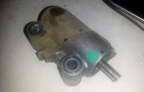
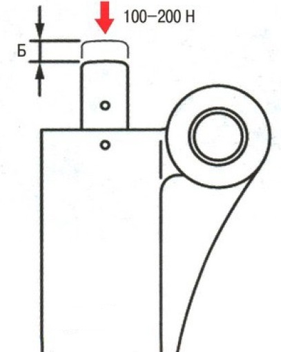
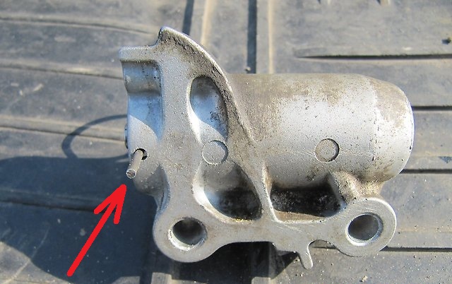
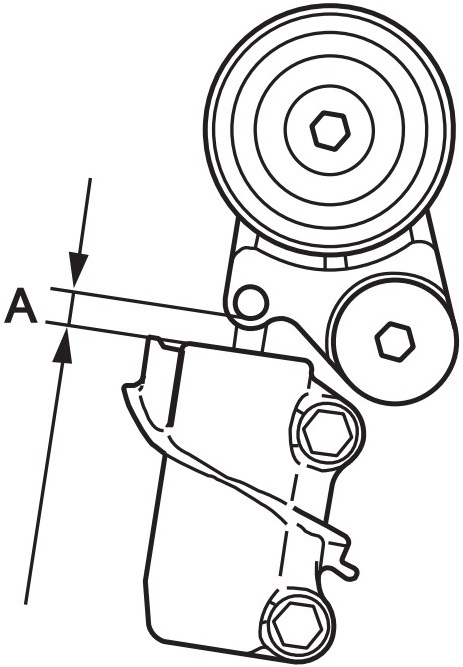
19. Visually check the auto tensioner. Check the tensioner rod for wear and damage. Measure the free protrusion of the tensioner rod.
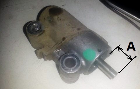
Note:
If protrusion A is less than 9.1 mm, replace the tensioner.
20. Rest the body of the tensioner against a rigid support and press on the rod with a force of 100-200 N. Measure stroke B of the rod. The stroke of a working tensioner should be no more than 3 mm.
Note:
This check can be done in a vice. If the stem sinks easily, replace the tensioner. If compression requires significant effort, the auto-tensioner is good.
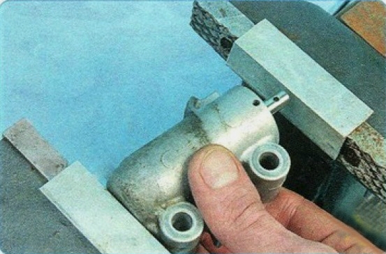
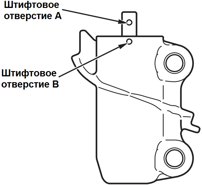
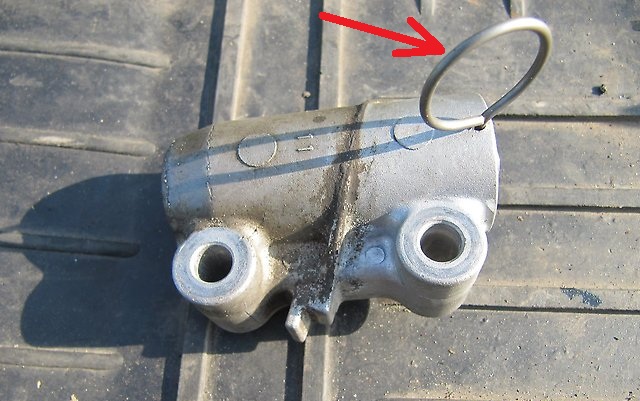
21. While slowly squeezing the tensioner in a soft-padded vise, push the auto tensioner rod down until the holes in the rod line up with the hole in the body.
Note:
To avoid deformation and damage to the tensioner, do not compress it too quickly.
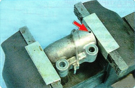
22. Insert a special hex wrench or pin (2 mm in diameter) into the aligned holes of the tensioner.
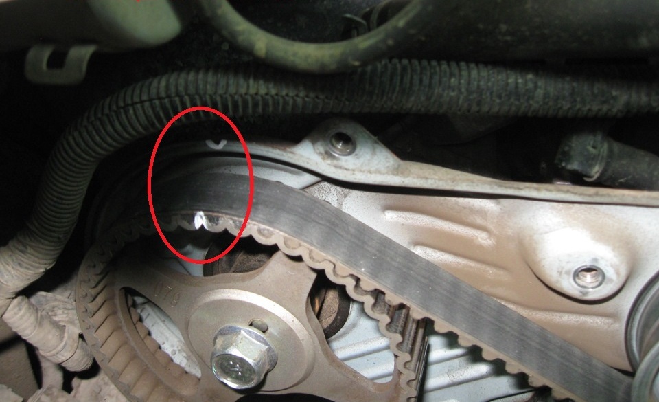
23. Install the tensioner on the Outlander HL engine by tightening its fastening bolts with a nominal torque of 23 ± 3 Nm.
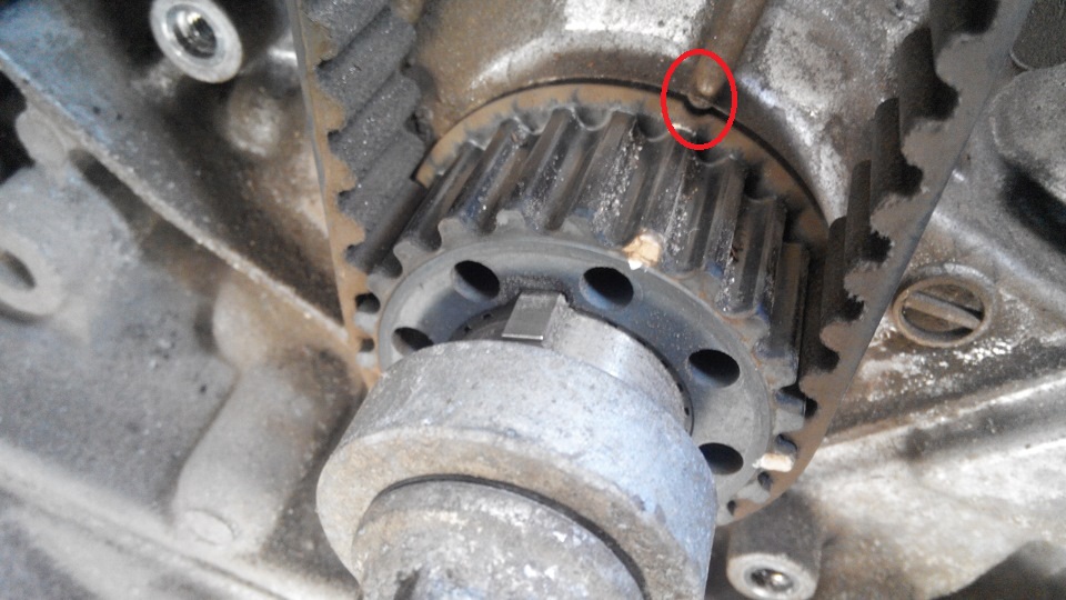
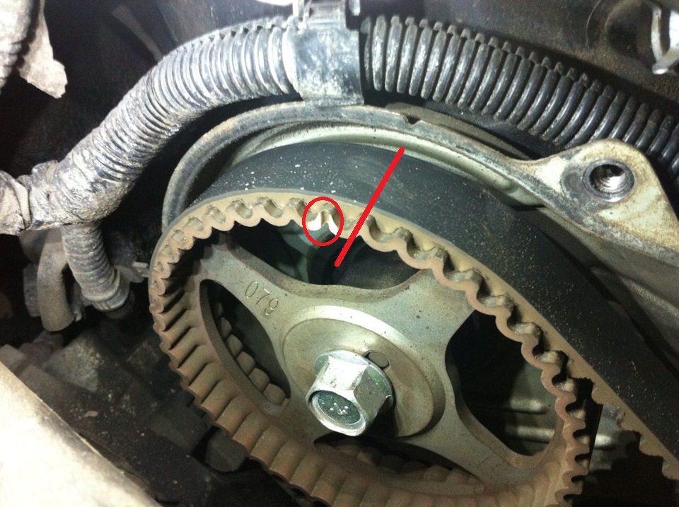
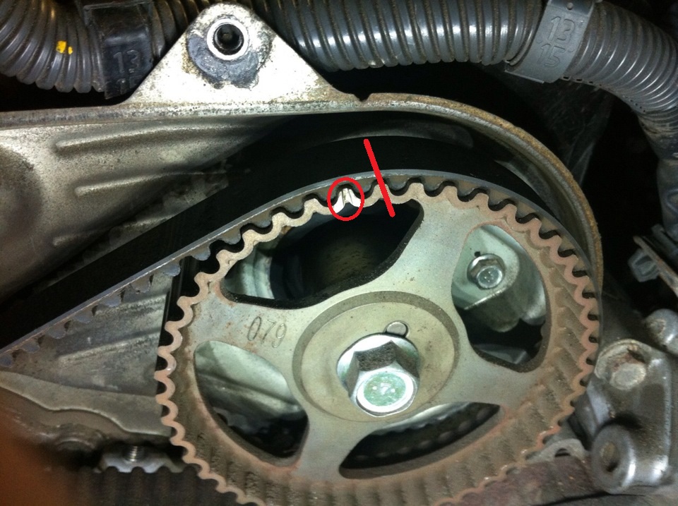
24. Check the timing marks of the Mitsubishi Outlander HL, their coincidence on the gears of the crankshaft and camshafts.
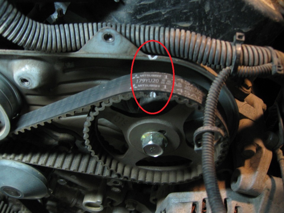
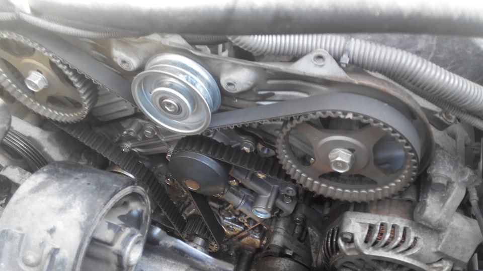
25. Put a new belt on the pulleys in the following order: crankshaft sprocket, water pump pulley, right camshaft sprocket, intermediate roller, left camshaft sprocket, tension roller.
Note:
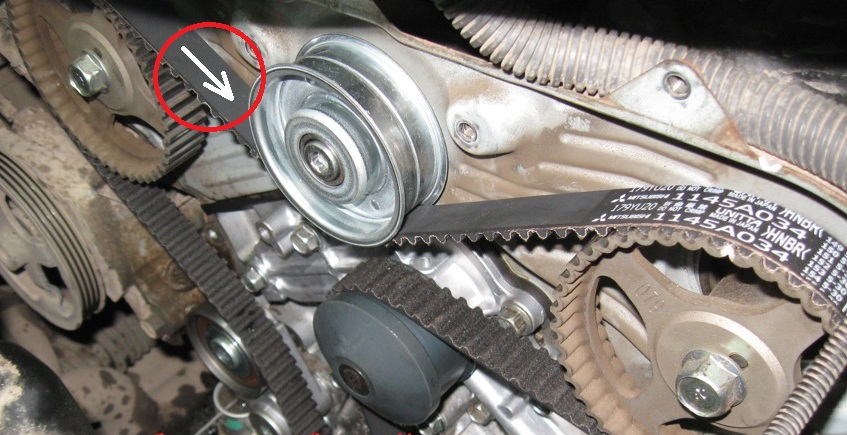
If there are arrows on the new belt, they should point in the direction the belt travels when the engine is running when installed.
26. Remove the fixing rod from the tensioner hole.
27. Screw the pulley mounting bolt into the crankshaft shank and turn the crankshaft for the bolt two turns clockwise. Check the matching of the alignment marks of the crankshaft and camshaft.
Note:
If not, reinstall the belt.
28. Check the tension of the timing belt. If the belt is tensioned correctly, the tensioner plunger should protrude from the housing by a distance A equal to 9.1-13.4 mm.
29. Install all removed parts in the reverse order of removal.
Note:
Rated tightening torque of the bolts for fastening the right support bracket to the engine block: M8 - 20 ± 5 Nm; M10 - 48 ± 11 Nm.
The nominal tightening torque of the timing cover bolts is 7 ± 1 Nm.
The article is missing:
- Tool photo
- Photo of parts and consumables
Source: carpedia.club