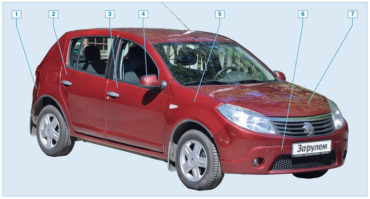
![1 generation [2009 - 2014]](/uploads/Renault_Sandero_2009-2014_.jpg)

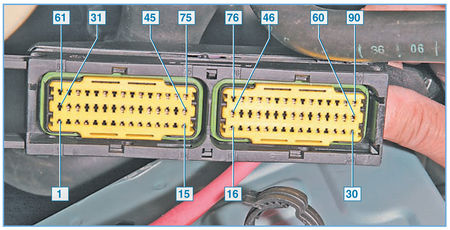
The numbering of the terminals of the ECU wiring harness block We
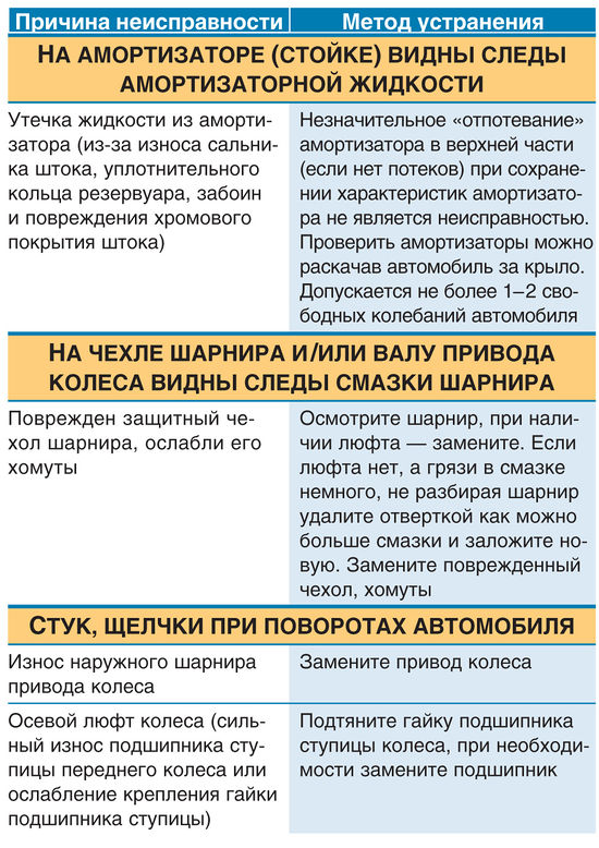
check the ignition coil and its electrical circuits when a malfunction is detected in the ignition system - in the absence of sparking on the spark plugs.
The ignition coil and the fuel pump are supplied with voltage from the battery through the F3 fuse (25 A) and then through the K5 relay (power circuit) installed in the engine compartment mounting block. The voltage to the relay winding (control circuit) K5 is supplied from the ignition switch through the fuse F02 (5 A) located in the mounting block in the passenger compartment.
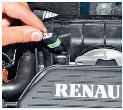
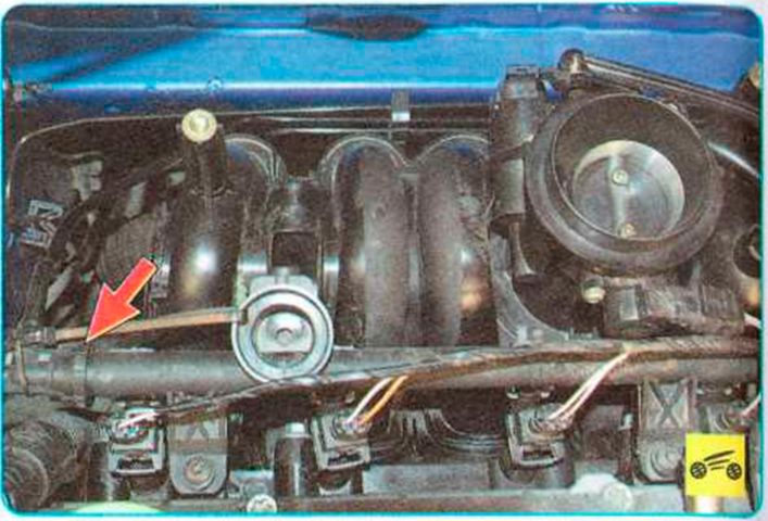
To check the power circuit of the ignition coil, disconnect (with the ignition off) from the coil the block of the wiring harness of the engine control system.
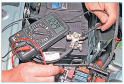
We connect the tester probes to terminal “C” of the wiring harness block and to the “mass” of the engine. Immediately after the ignition is turned on (while the fuel pump is running) ...
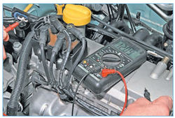
... the device should detect a voltage approximately equal to the battery voltage.
If there is no voltage at terminal “C” of the wiring harness block, then the fuses, the contact group of the ignition switch, the K5 relay or their electrical circuits may be faulty.
With the ignition off, remove the K5 relay from the mounting block in the engine compartment and disconnect the wiring harness block from the ignition coil. We connect the tester probes (in ohmmeter mode) to socket “5” of the relay and to terminal “C” of the ignition coil wiring harness block.
If the tester shows "infinity" - there is an open in the circuit.
If the circuit is working, we check whether “+12 V” is supplied from the battery to socket “3” of relay K5.
For this…
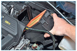
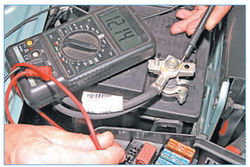
... we connect the “positive” probe of the tester to the relay socket, and the “negative” probe to the “-” terminal of the battery.
If there is no voltage, check the F3 fuse (25 A). If the fuse is good, check the circuit from the fuse socket to the relay socket.
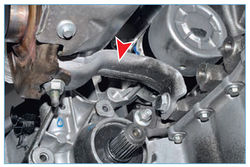
To do this, remove the fuse ...

... and connect the tester probes (in ohmmeter mode) to socket "S2" (shown in the photo) of the fuse and to socket "3" of the relay.
If the tester shows infinity, there is an open in the circuit. If the circuit is OK, we check whether “+12 V” is supplied from the battery to another fuse socket.
For this…

... we connect the “positive” probe of the tester to the “E2” socket (shown in the photo) of the fuse, and the “negative” probe to the “-” terminal of the battery.
The tester should show battery voltage. Otherwise, the circuit is faulty (open or short to ground) from the battery to the fuse socket.
To check the control circuits of the K5 relay, we disconnect (with the ignition off) the block of the wiring harness of the engine control system from the computer.
We connect the tester probes (in ohmmeter mode) to socket "2" of the relay and terminal "67" of the ECU wiring harness block. If the tester shows "infinity", this means an open in the control "negative" circuit of the relay.
If the "negative" control circuit of the relay is working, we check whether "+12 V" is supplied to the socket "1" of the relay.
For this…
... we connect the "positive" probe of the tester to the socket "1" of the relay, and the "negative" probe to the "-" terminal of the battery.
With the ignition on, the tester should show the voltage of the battery. If there is no voltage, we check the F02 fuse installed in the mounting block in the cabin. If the fuse is intact, we check the circuit from the fuse socket to socket "1" of the relay and the circuit from the other fuse socket to terminal "3" of the ignition switch wiring harness block.
A tester with a 1-2 W lamp can be used to test the ignition coil control circuits.
We relieve pressure in the engine power system and do not connect the engine control system wiring harness block to the fuel module connector. We disconnect the block of the wiring harness from the ignition coil and connect the probe probes to the terminals "C" and "A" of the block of the wiring harness. If the probe probes do not fit into the terminal sockets of the block, we insert pieces of bare wires into the sockets (you can use pins).
With a working coil power circuit and control circuit while cranking the crankshaft with a starter ...
…the probe light should flash rapidly.
Otherwise, we check for an open and a short to ground the wire connecting terminal “A” of the coil wiring harness block with terminal “32” of the ECU wiring harness block.
Similarly, by connecting the probe probes to terminals “C” and “B” of the ignition coil wiring harness block, and then to terminal “B” of the coil wiring harness block and to terminal “1” of the computer wiring harness block, we check another ignition coil control circuit.
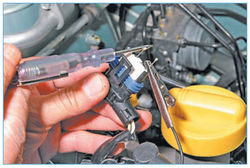
You can check the serviceability of the ignition coil itself on the engine by disconnecting the wiring harness block and high-voltage wires from it.
To check one of the primary windings of the ignition coil, we connect the tester probes to the terminals "C" and "A" of the coil.
In ohmmeter mode, we check the winding for an open circuit.
If the tester shows "infinity" - a break has occurred in the winding.
Similarly, by connecting the tester probes to the terminals “C” and “B” of the coil, we check the other primary winding of the coil for an open.
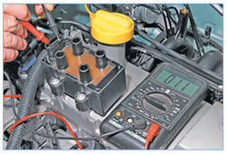
To check for an open circuit in the secondary winding of the ignition coil, we connect the tester probes to the paired high-voltage coil terminals (terminals 1-4 or 2-3 cylinders).
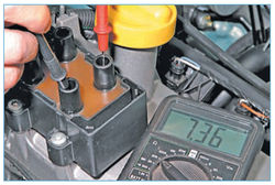
For a working ignition coil, the tester should record a resistance of about 7.0 kOhm.
If the secondary winding breaks, the tester will show "infinity".
Similarly, we check the other secondary winding of the ignition coil.
We check the secondary windings of the ignition coil for breakdown on the engine. We relieve pressure in the engine power system and do not connect the wiring harness block to the fuel module connector.
Two known-good spark plugs are required for testing.
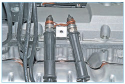
We connect the bodies of the candles with a piece of uninsulated wire (“massaging”).
We connect the paired leads of the ignition coil with candles with serviceable high-voltage wires and place the candles on the cylinder head cover. Turn the crankshaft with the starter.
Warning: To avoid electric shock, do not touch spark plugs or high voltage wire lugs.
With a working ignition coil, sparks should regularly jump between the electrodes of the candles. Similarly, by connecting the high-voltage wires to the other two paired terminals of the coil, we check the other secondary winding for breakdown.
Source: http://wiki.zr.ru/68_%D0%94%D0%B8%D0%B0%D0%B3%D0%BD%D0%BE%D1%81%D1%82%D0%B8% D0%BA%D0%B0_Stepway