![1 generation [2003 - 2007]](/uploads/Mitsubishi_Outlander_I_2003_-_2008_.jpg)
![3 generation [2012 - 2014]](/uploads/3.png)
![XL [2005 - 2012]](/uploads/4d137205da66f_.jpg)

Tools:
- Knife
- torque wrench
- Head 10 mm
- Head 12 mm
Parts and consumables:
- Cleaner (or solvent)
- Plastic gauge Plastigauge PL-X (0.018 - 0.045 mm)

- rags
Notes:
How to remove the camshafts and what tools are used for this, see here .
This method of checking camshafts and cylinder head greatly simplifies the procedure for determining clearances in head parts such as camshaft bearings.
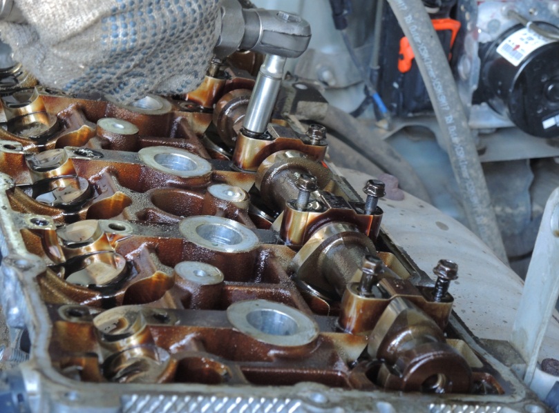
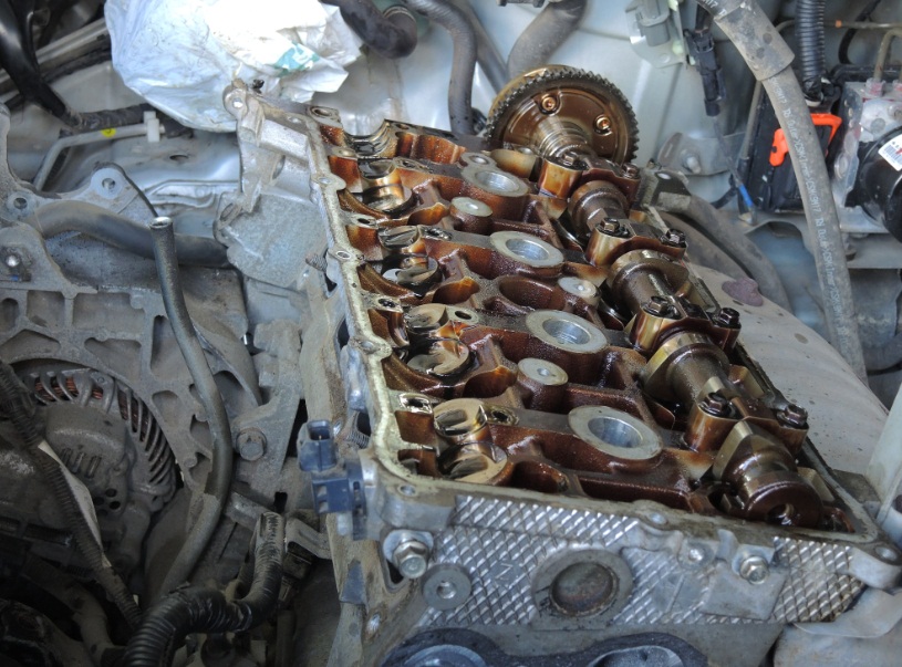
1. Clean the camshaft beds on the cylinder head, camshaft bearing caps and shaft journals from oil and grease deposits.
2. Install the lower exhaust camshaft bearing shell onto the cylinder head, then carefully place the Mitsubishi Outlander HL camshaft.
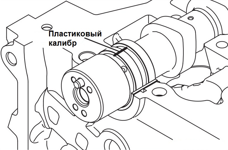
3. Cut off a piece of plastic gauge with a length that matches the width of the neck, then put it on the camshaft neck along its axis.
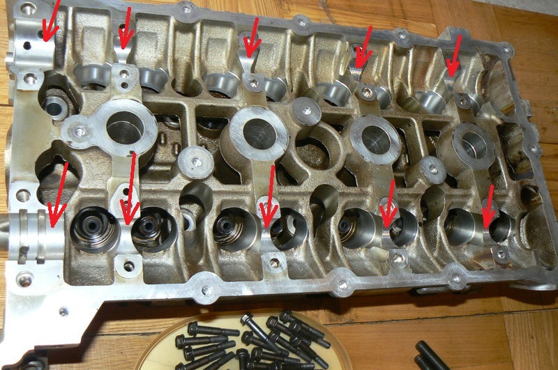
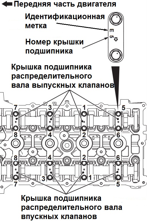
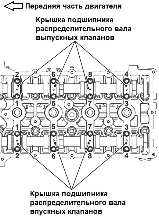
4. Carefully install the camshaft bearing caps on the cylinder head and tighten the mounting bolts to the nominal torque in two or three steps in the order shown in the figure. Tightening torque: passage 1 - 6 ± 1 Nm; passage 2 - 12 ± 1 Nm.
Note:
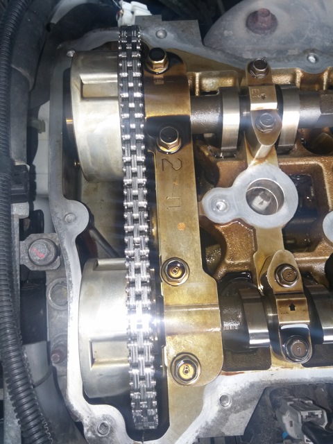
Since the camshaft bearing caps with oil feed and the camshaft thrust bearing caps have the same shape as other bearing caps, for correct installation, check that the identification mark and number of the caps correspond with the installation location (inlet and exhaust valve side identification) and the bearing number:
I - intake camshaft:
E - exhaust camshaft.
5. Install the upper camshaft bearing onto the camshaft.
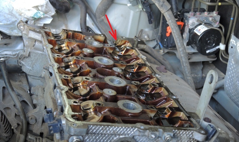
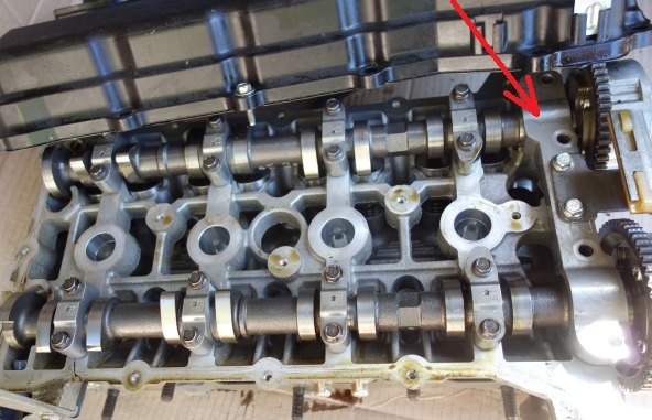
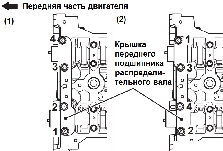
6. Install the front camshaft bearing cover on the cylinder head and tighten the cover fastening bolts to the specified torque of 17 ± 3 Nm in the sequence of numbers indicated on the left side of the figure (1).
Note:
If the front camshaft bearing cover is installed incorrectly (at an angle), it may be damaged when tightening the fastening bolts.
Install the front camshaft bearing cap onto the cylinder head and camshafts correctly.
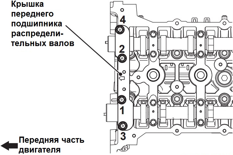
7. Finally tighten the camshaft front bearing cap bolts to a nominal torque of 30 ± 2 Nm in the sequence of numbers shown on the right side of the figure (2) above.
8. Turn away bolts of fastening of a cover of the forward bearing of camshafts in two-three steps in the order specified in drawing, and remove a cover.
Note:
Be careful not to drop the upper camshaft bearing.
9. Turn away bolts of fastening of covers of bearings of camshafts in four-five receptions in the sequence specified in drawing, and carefully remove covers.
Note:
If the camshaft bearing cap bolts are loosened in one go, the movement of the camshaft under the force of the valve springs can lead to the bolts pulling out and damage to their threads.
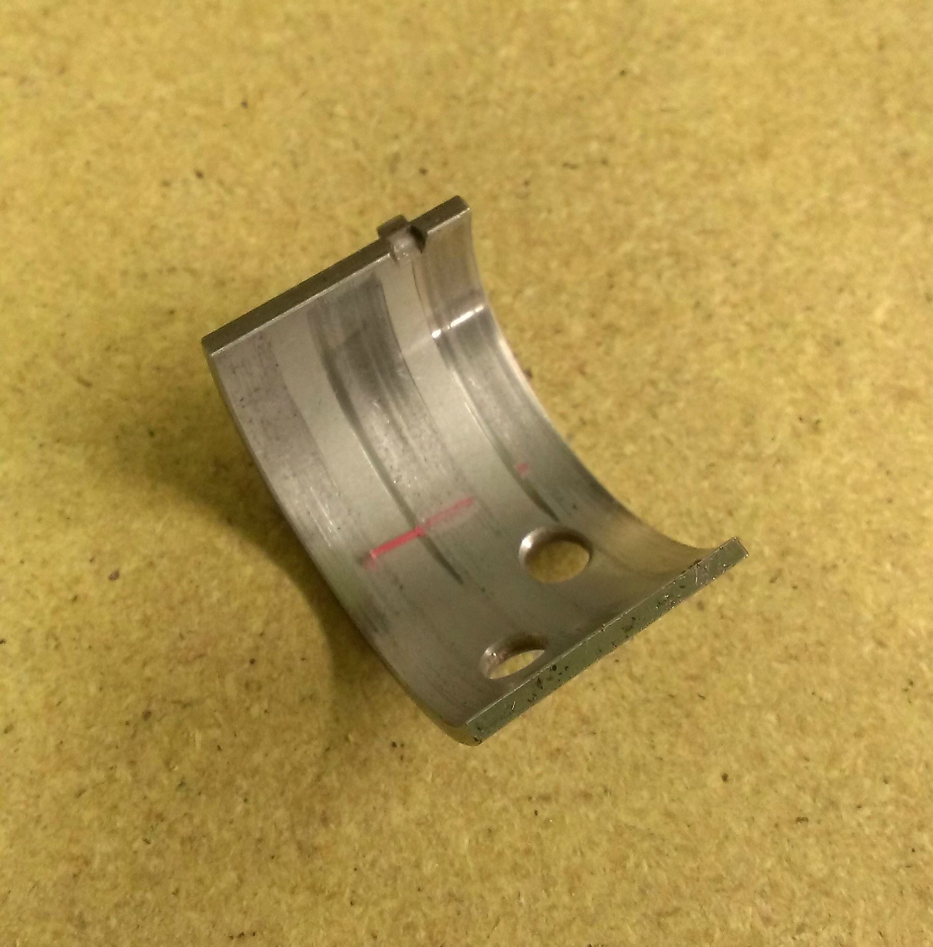
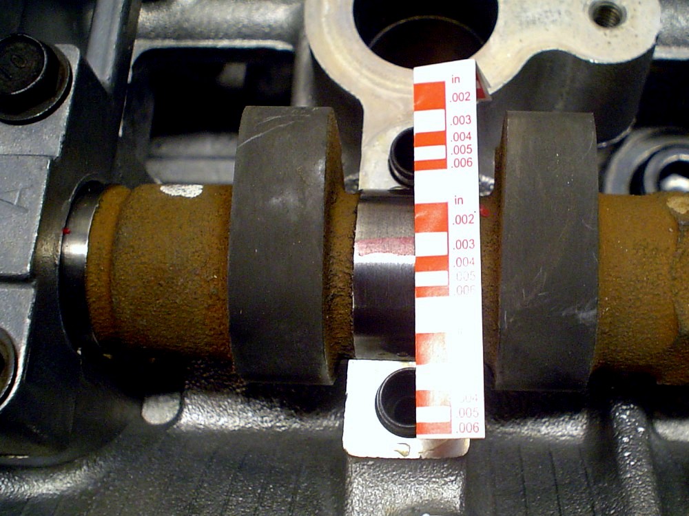
10. Measure the width of the crushed plastic gauge wire at its widest point using the scale printed on the plastic gauge package. For comparison, nominal camshaft oil clearances are 0 - 0.032 mm.
The article is missing:
- Tool photo
- Photo of parts and consumables
Source: carpedia.club