![1 generation [restyling] [2000 - 2010]](/uploads/Skoda_Octavia_2000_-_2010_.jpg)
![2 generation [2004 - 2008]](/uploads/Skoda_Octavia_2004_-_2012_.jpg)
![3 generation [2013 - 2017]](/uploads/Skoda_Octavia_2013_-_2015_.jpg)

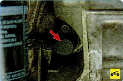
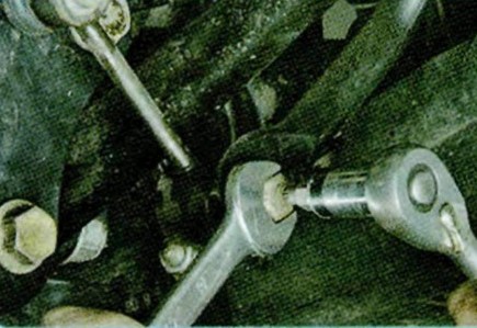
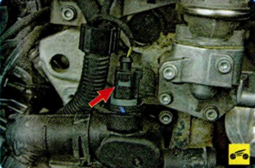
The inductive type crankshaft position sensor is designed to synchronize the operation of the electronic control unit with the TDC of the pistons of the 1st and 4th cylinders and the angular position of the crankshaft.
The sensor is installed at the rear of the engine block.
As the crankshaft rotates, the sensor's magnetic field changes, inducing AC voltage pulses. The control unit determines the speed of the crankshaft from the signals of the sensor and issues impulses to control the engine.
A malfunction of this sensor causes a complete failure of the engine control system: in the absence of its signal, it is impossible to start the engine.
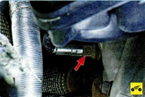
The control oxygen concentration sensor is used in the feedback fuel injection system. To correct the calculations of the duration of the injection pulses, information about the presence of oxygen in the exhaust gases is used, this information is provided by the control oxygen sensor. The oxygen contained in the exhaust gases reacts with the sensitive element of the sensor, creating a potential difference at the sensor output. The potential difference varies from approximately 0.1 V (high oxygen content - lean mixture) to 0.9 V (low oxygen content - rich mixture).
The control oxygen concentration sensor is installed on the exhaust manifold. For normal operation, the temperature of the sensor must not be lower than 300 ° C, therefore, for quick warm-up after starting the engine, a heating element is built into the sensor and, in addition, the engine is equipped with an additional air supply system, the main purpose of which is to ensure exhaust toxicity standards during a cold start of the engine
By monitoring the output voltage of the concentration sensor oxygen, the ECU determines which command to adjust the composition of the working mixture to apply to the injectors. If the mixture is poor (low potential difference at the output of the sensor), then a command is given to enrich the mixture; if rich (high potential difference) - a command to lean the mixture.
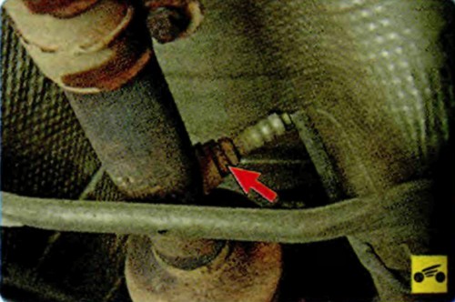
The diagnostic oxygen concentration sensor is installed after the converter, it works on the same principle as the control sensor, and is completely interchangeable with it. The signal generated by the diagnostic oxygen concentration sensor indicates the presence of oxygen in the exhaust gases after the converter. The effectiveness of the converter is evaluated by the engine control unit by comparing the signals of the control and diagnostic sensors. If the converter is working properly, the readings of the diagnostic sensor will differ significantly from the readings of the control sensor. The same readings indicate a malfunction of the converter.
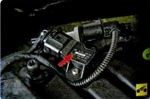
The intake manifold absolute pressure and temperature sensor detects the change in pressure and temperature in the intake manifold depending on the change in load and engine speed and converts it into an output signal voltage. Depending on the information received from the sensor, the ECU regulates the amount of fuel injected and the ignition timing.
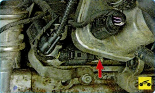
The camshaft position sensor (phase sensor) of the inductive type is installed at the rear of the cylinder head behind the throttle assembly. When the camshaft rotates, the protrusions on its master disk change the magnetic field of the sensor, inducing AC voltage pulses. The sensor signals are used by the ECU to organize phased fuel injection in accordance with the firing order of the cylinders. If a malfunction occurs in the camshaft position sensor circuit, the ECU memorizes its code and turns on the signal pump.
The coolant temperature sensor measures the coolant temperature and sends a signal to the control unit. The sensor is made in the form of a thermistor that is sensitive to temperature changes. The electrical resistance of the sensor decreases with increasing temperature. The ECU processes the sensor signal and sets the optimal enrichment of the working mixture when the engine warms up.
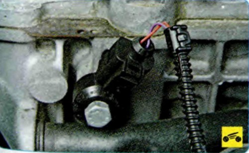
The knock sensor is attached to the top of the cylinder block on the intake pipe side and detects abnormal vibrations (knock) in the engine.
The sensitive element of the sensor is a piezoelectric plate. During detonation, voltage pulses are generated at the output of the sensor, which increase with increasing intensity of detonation impacts. The ECU, based on the signal from the sensor, regulates the ignition timing to eliminate detonation flashes of fuel.
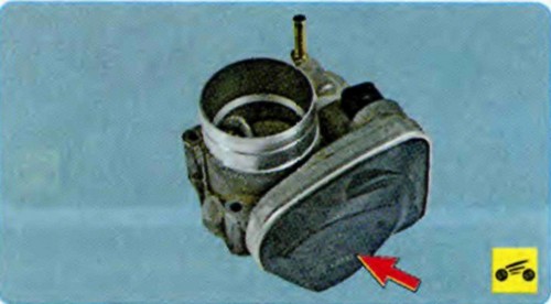
The throttle position sensor (TPS) is installed on the side of the throttle assembly (under the cover) and is connected to the throttle valve axis
. It is a potentiometer, one end of which is supplied with a “plus” of the supply voltage (5 V), its other end is connected to the “ground” . From the third output of the potentiometer (from the slider) there is an output signal to the ECU. As the throttle valve is turned, the sensor output voltage changes. When the throttle is closed, it is below 0.5 V. When the throttle opens, the voltage at the sensor output rises and should be more than 4 V when the throttle is fully open. By monitoring the sensor output voltage, the ECU adjusts the fuel supply depending on the throttle opening angle
In the event of a throttle sensor failure, the ECU memorizes the sensor's fault code, turns on the engine management system warning light, and calculates the estimated throttle valve opening angle value from the crankshaft speed and from the signals from the temperature and absolute air pressure sensors in the intake manifold.
See also: Removing and installing the ignition lock.
Source: http://skoda-octavia2.ru/index.php/skhema-elektrooborudovania/215-sistema-upravleniya-dvigatelem.html