![P12 [2001 - 2008]](/uploads/Nissan_Primera_Primera_1.9_DCi_Sedan.jpg)

Tools:
- Flat feeler set
- Washer puller
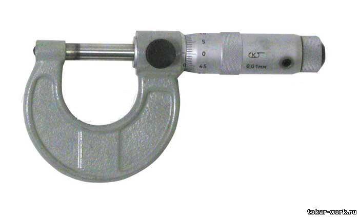
- Micrometer
- Open-end wrench - 10 mm
- Open-end wrench - 17 mm
- Nozzle on the collar - 10 mm
- Nozzle on the collar - 13 mm
- Nozzle on the collar - 17 mm
- Collar for end nozzle
- Small flat screwdriver
Parts and consumables:
- washers
Notes:
To compensate for the thermal expansion of the valve, a gap is set between the end of the valve stem and the camshaft cam. With an increased clearance, the valve will not open fully, with a reduced clearance, it will close completely.
The gap is measured with a feeler gauge on a cold (at a temperature of + 20 degrees) or a warm engine (at operating temperature) between the camshaft cams (the cam must be directed away from the pusher) and the valve lifter shim.
The nominal clearance for a cold engine on the intake camshaft is 0.25-0.33 mm, on the exhaust shaft - 0.32-0.40 mm.
The nominal clearance for a hot engine on the intake camshaft is 0.304-0.416 mm, on the exhaust shaft - 0.348-0.472 mm.
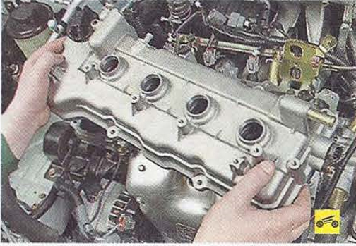
1. Remove the cylinder head cover.
2. Set the piston of the 1st cylinder to the TDC position of the compression stroke. More details here .
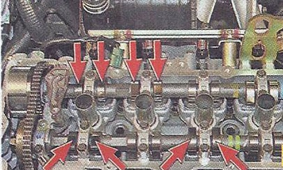
3. Measure with a set of probes the clearances in the drive of those valves, the cams of which are directed upwards from the pushers.
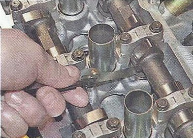
Notes:
In this case, these are the intake valves of the 1st and 2nd cylinders and the exhaust valves of the 1st and 3rd cylinders. Record the measured clearances.
4. Rotate the crankshaft 360 degrees. (at TDC of the compression stroke of the 4th cylinder) and measure the clearances in the drive of the remaining valves.
5. If the clearances in the valve drive deviate from the norm, remove the washers and calculate their thickness using the formulas below. To remove the washers, use a special tool or remove the camshafts.
Notes:
Formulas for calculating the thickness of the washer:
1 - For inlet valves N = R + (M - 0.37);
2 - For exhaust valves N = R + (M - 0.40),
where N is the thickness of the new washer, mm; R - thickness of the removed washer, mm; M - measured - valve clearance, mm.
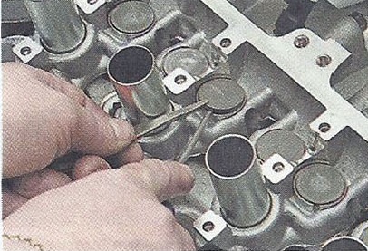
6. In order to make it easier to remove the adjusting washer, a groove is made in the pusher.
Note:
Use a screwdriver to turn the pusher by the groove so that it is convenient to pry the washer.
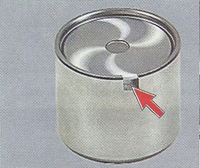
The back side of the washer is marked with its thickness (in this case, "244" means 2.44 mm)
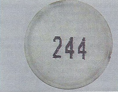
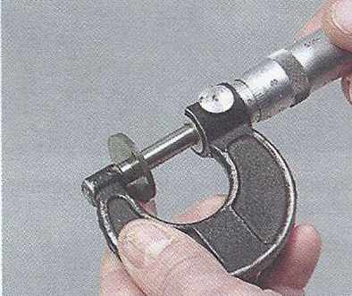
If there are no marks, measure the washer thickness with a micrometer. Repair kits include 73 types of washers with a thickness of 2.00 to 2.98 mm.
7. Put new washers into the pushers, calculated according to the formula given in paragraph 5, reinstall the camshafts and check the clearances. If necessary, repeat steps. 5-6.
8. Install all previously removed parts in the reverse order of removal.
The article is missing:
- Tool photo
- Photo of parts and consumables
- High-quality repair photos
Source: Nissan Primera P12 Operation, Maintenance and Repair Manual. Publishing house "Third Rome".