![1 generation [2011 - 2017]](/uploads/Lada_Granta_2011_-_2015.jpg)

Tools (for 8-valve engines):
- 5mm hex wrench
- Ratchet wrench
- Extension
- Head for 8 mm
- Head 10 mm
- High head 13 mm
- Head 15 mm
- Head 17 mm
- Head 19 mm
- Head 30 mm
- Torx socket E8
- Socket Torx E10
- Torx socket E12
- Head Torx E14
- 12 mm hex bit head
- Open-end wrench 8 mm
- Open end wrench 10 mm
- Open end wrench 13 mm
- Open-end wrench 17 mm - 2 pcs.
- Open end wrench 19 mm
- Straight ring wrench 8 mm
- Straight ring wrench 15 mm
- Straight ring wrench 17 mm
- Straight ring wrench 19 mm
- Ring wrench curved 8 mm
- 13 mm bent box wrench
- torque wrench
- Collar for end nozzle
- Nozzle on the collar 17 mm
- Screwdriver flat medium - 2 pcs.
- Small flat screwdriver
- Phillips screwdriver, medium
- Large flat screwdriver or spatula
- Jack or pit lift
- balloon wrench
- Special wrench for turning the tensioner roller (or snap ring remover)
- Key for fixing the camshaft pulley (or extension for the end cap on the crank)
- Funnel
- Pliers
- Kerner
- Hose
- Adjustable stop - 2 pcs.
- Hammer big
- Metal brush
- Stand
- lifting device
- Universal puller (if necessary)
- Calipers
- Micrometer
- Engine repair stand
- Marker
- Knife (or scraper)
- Compressor
- Air blow gun
- Piston pin mandrel
- Scraper
- Hammer (soft-faced)
- Piston ring remover
- Piston ring compression mandrel
- Valve adjuster
- Tweezers
Tools (for 16-valve engines):
- Open-end wrench 8 mm
- Open end wrench 10 mm
- Open end wrench 13 mm
- Open-end wrench 17 mm - 2 pcs.
- 19 mm open-end wrench
- Straight ring wrench 8 mm
- Straight ring wrench 13 mm
- Straight ring wrench 15 mm
- Straight ring wrench 17 mm
- Straight ring wrench 19 mm
- Corner wrench curved 8 mm
- 13 mm bent box wrench
- Collar for end nozzle
- Nozzle on the collar 17 mm
- Jack or pit lift
- balloon wrench
- Stand
- lifting device
- Screwdriver flat medium
- Small flat screwdriver
- Phillips screwdriver, medium
- Large flat screwdriver or spudger
- Pliers
- 5mm hex wrench
- Ratchet wrench
- Extension
- Head for 8 mm
- Head 10 mm
- High head 13 mm
- Head 15 mm
- 16mm high socket or spark plug wrench
- Head 17 mm
- Head 19 mm
- Head 30 mm
- Head Torx E8
- Socket Torx E10
- Torx socket E12
- Head Torx E14
- Funnel
- Kerner
- Hose
- Adjustable stop - 2 pcs.
- Hammer big
- Metal brush
- torque wrench
- Special wrench for turning the tensioner roller (or snap ring remover)
- Key for fixing the camshaft pulley
- Calipers
- Micrometer
- Engine repair stand
- Knife (or scraper)
- Compressor
- Air blow gun
- Piston pin mandrel
- Flat feeler set
- Scraper
- Hammer (soft-faced)
- Piston ring remover
- Piston ring compression mandrel
- Valve adjuster
- Tweezers
Parts and consumables:
- Shoe - 2 pcs.
- Guide pin М12×1.25 mm with sawn slot for a screwdriver
- Solvent
- Petrol
- Conrod bearing set
- Set of liners indigenous
- Set of persistent half rings
- Motor oil
- Coolant
- Transmission oil
- Grease
- Sealing ring of a tube of an oil receiver
- Piston ring kit
- Head gasket (for 8-valve engines)
- Sealant-gasket type LOCTITE 5910 (for 16-valve engines)
- Block head bolts (if necessary)
- Sealant type LOCTITE 574
- Oil pump gasket
- Throttle gasket (if necessary)
- Heat Resistant Sealant
- Grease
- Anaerobic Threadlocker
- Grease "SHRUS-4"
- wooden bars
- Degreaser
- Adjusting washers (if necessary)
- rags
Note:
Before assembling the engine, clean the mating surfaces of the cylinder block under the block head, oil pan, oil pump, coolant pump and its pipe, crankshaft rear oil seal holder from old gaskets, sealant and oil.
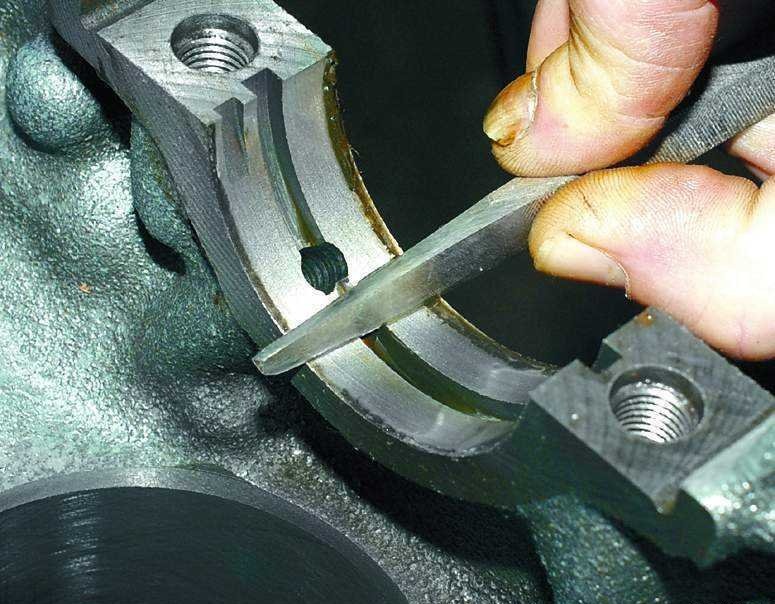
1. Clear a deposit on the edges of beds of the block of cylinders. Clean deposits from oil grooves in beds.
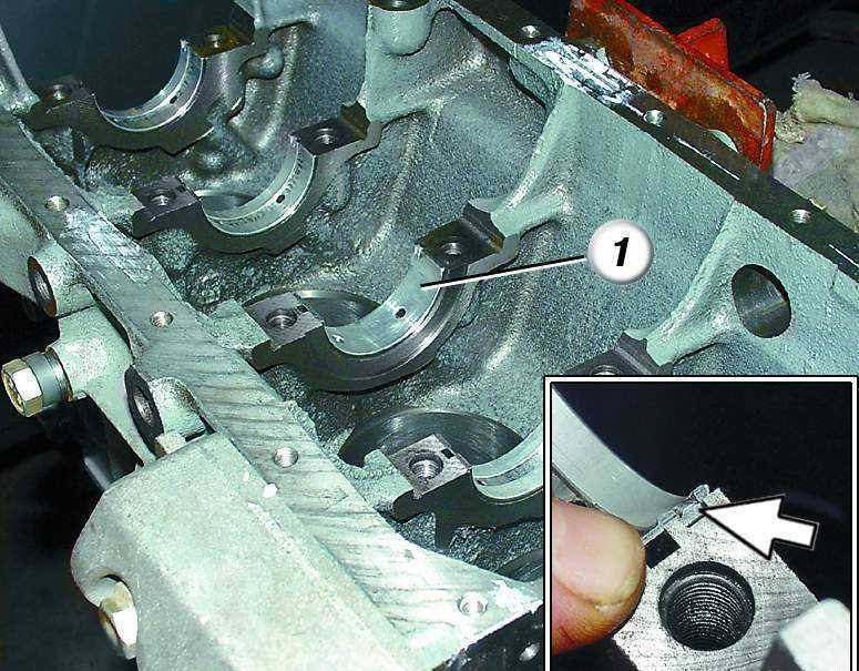
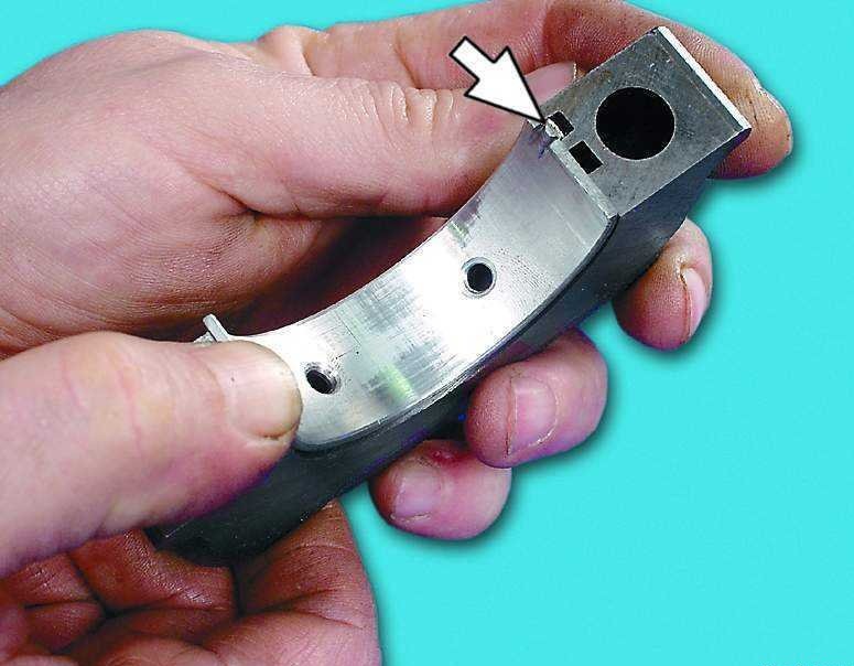
2. Establish loose leaves of radical bearings in bed of the block of cylinders according to the labels made at dismantling. Please note that the middle liner 1 is without a groove. When installing the liners, their locking antennae must enter the grooves of the beds. Lubricate the liners with engine oil.
3. Lubricate the main bearing shells with engine oil.
Note:
After installing the main bearing shells in bed, their ends protrude slightly, therefore, for the correct orientation of the liners, when final tightening the bearing cap bolts, make sure that the protrusion of both ends is the same.
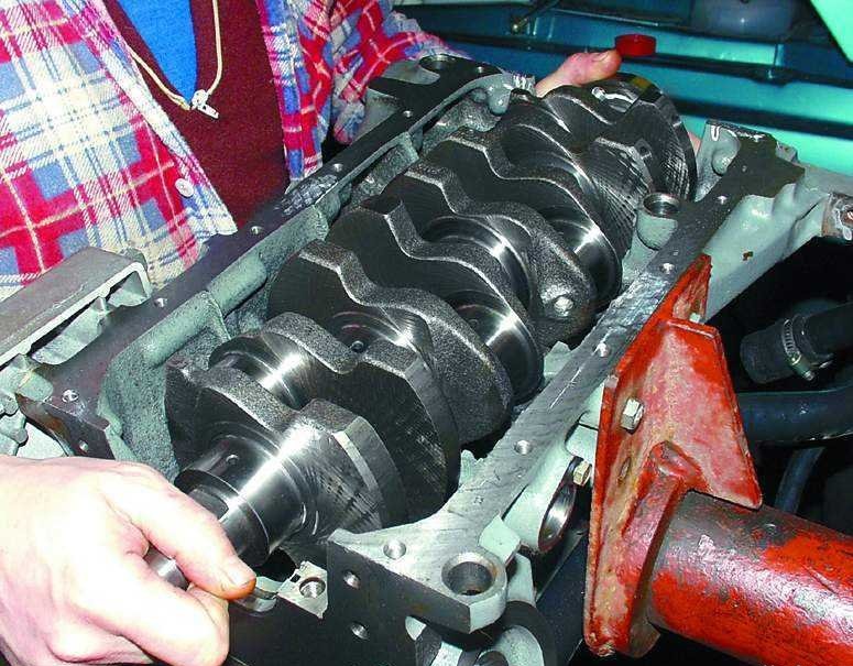
4. Install the crankshaft in the cylinder block.
5. Grease persistent half rings with engine oil.
Note:
Pay attention to the grooves of the thrust half rings: these sides of the half rings must be installed against the cheeks of the crankshaft.
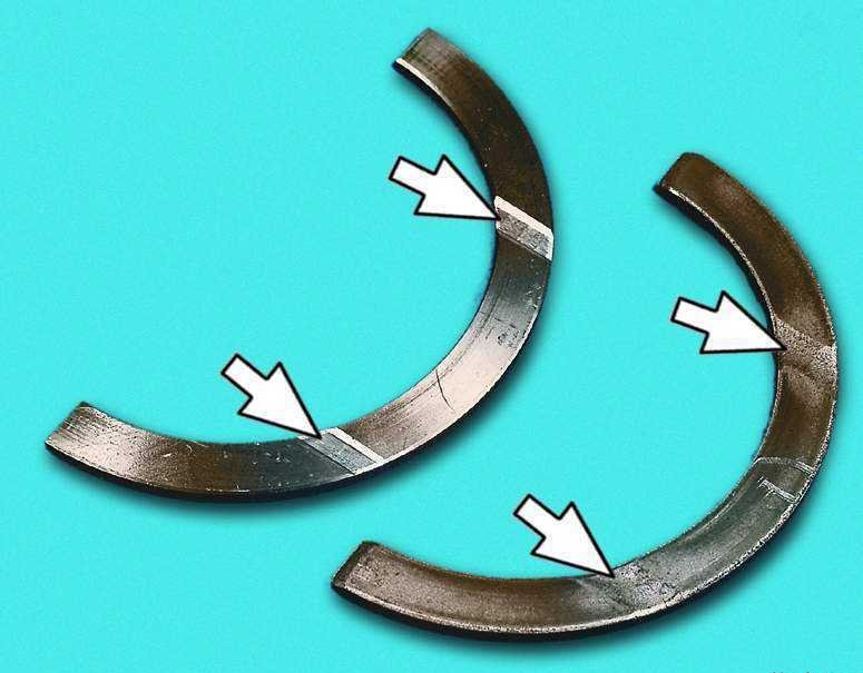
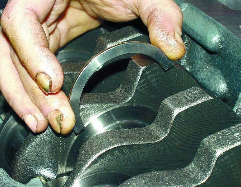
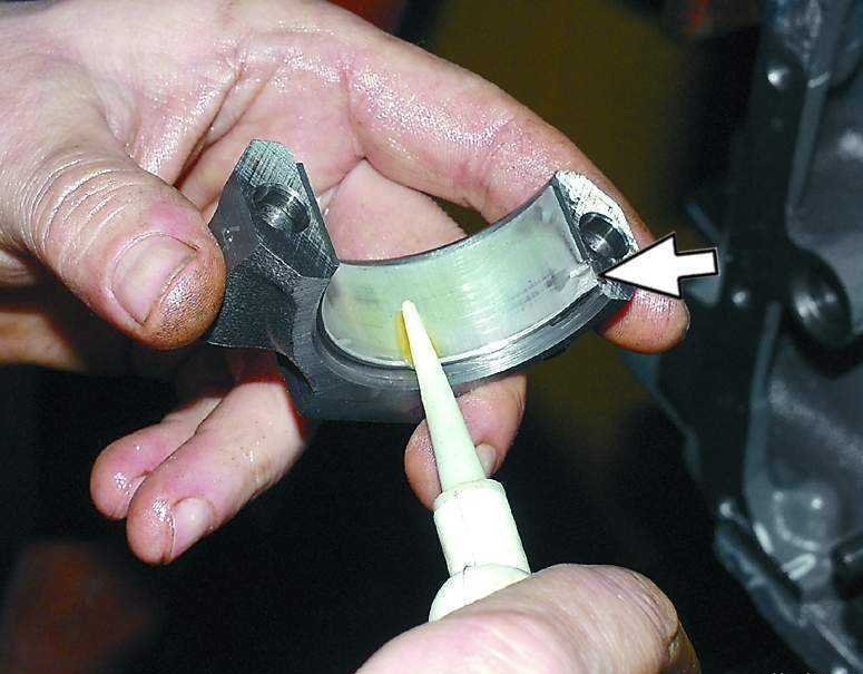
6. Install a steel-aluminum semi-ring (white) from the front side of the middle bed (from the side of the camshaft drive).
7. Install a ceramic-metal semi-ring (yellow) - on the other side of the bed.
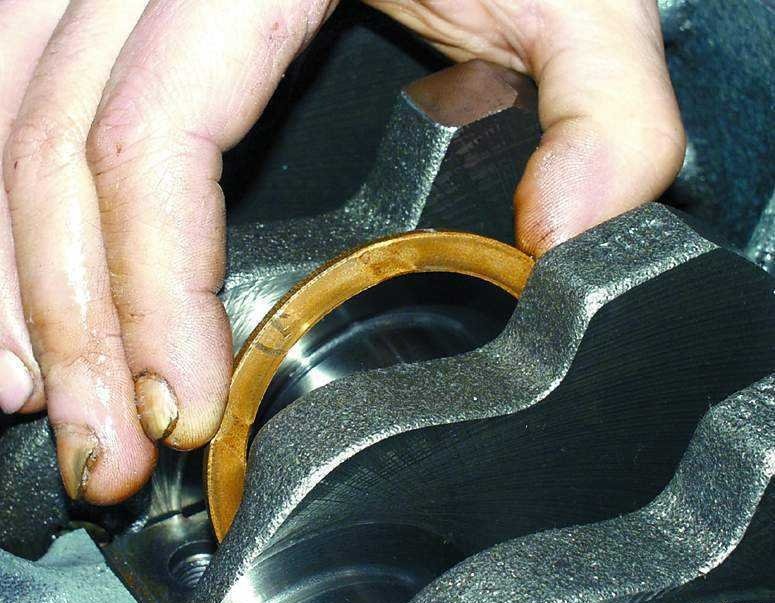
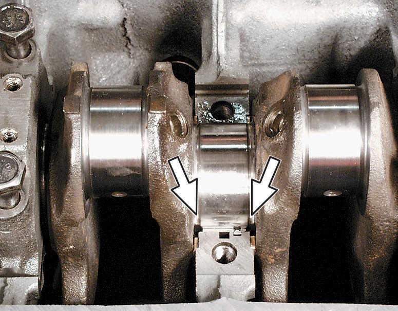
8. Turn the half rings so that their ends are flush with the ends of the bed.
9. Insert loose leaves into covers of radical bearings according to the labels applied when dismantling the engine. In this case, the locking antennae of the main bearing shells must enter the grooves of the main bearing caps.
10 . Lubricate the main bearing shells with engine oil.
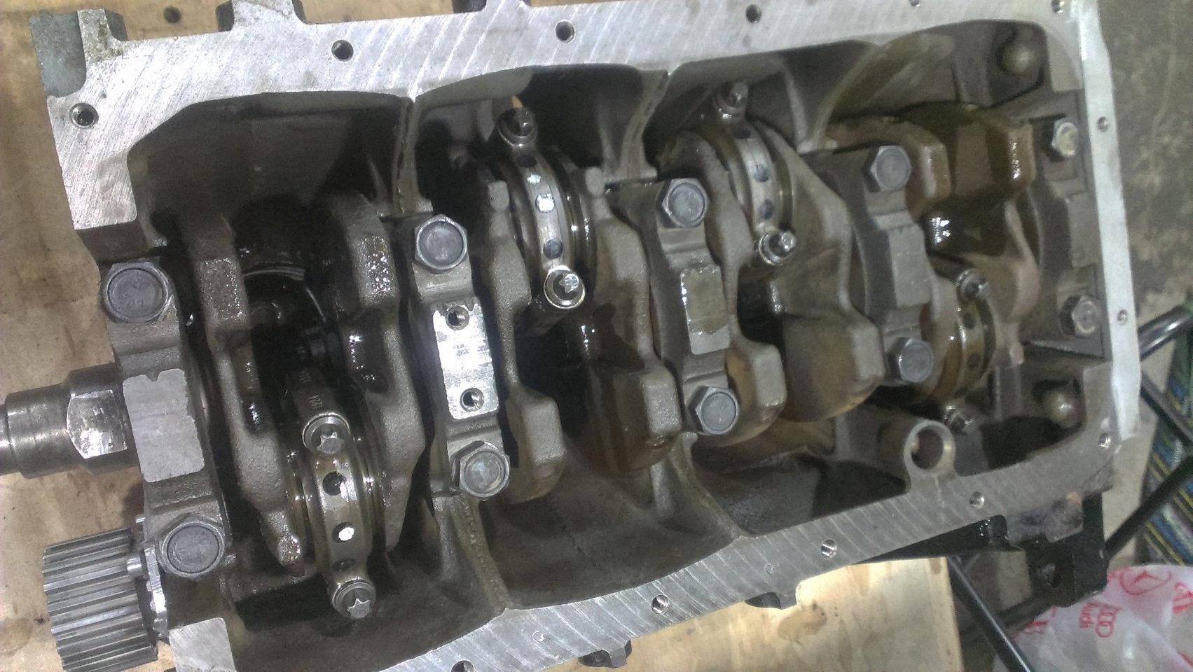
11. Establish covers of radical bearings according to labels.
Note:
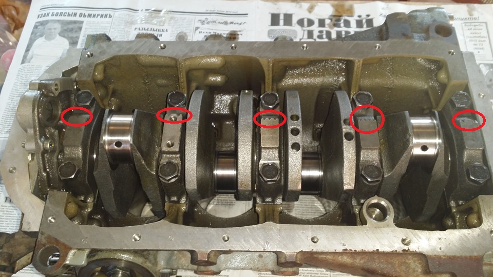
The main bearing caps are marked (notches) in accordance with the cylinder number. The exception is the fifth cover, on which two marks are applied, as well as on the second one. On the second cover there are two threaded holes A for the oil receiver mounting bolts. In this case, the cylinder numbers are considered from the side of the camshaft drive, and the covers are installed with marks towards the generator bracket.
Use a soft-faced hammer made of brass, lead, or polyurethane to install the crankshaft main bearing caps. It is forbidden to install the main bearing caps by tightening the fasteners, as this will damage the seating surfaces of the caps and the cylinder block.
12 . Lubricate the threads and ends of the heads of the bolts of the main bearing caps with engine oil.
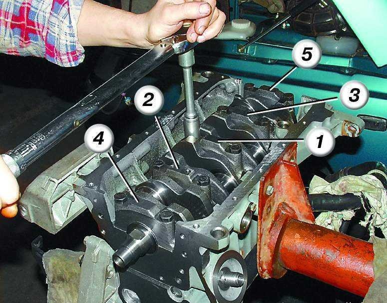
13. Wrap the bolts and tighten them to the required torque in the following order: first tighten the bolts of the third main bearing cap 1, then the second 2 and fourth 3, then the first 4 and fifth 5. After tightening the bolts, turn the crankshaft 2-3 turns - it should rotate easily, without jamming.
14. Establish the oil pump and wrap bolts of its fastening.
Note:
For ease of installation, apply a light coat of grease to the rear oil seal retainer gasket and “glue” it to the cylinder block. Remove excess grease.
15. Establish the holder of a back epiploon and wrap bolts of its fastening.
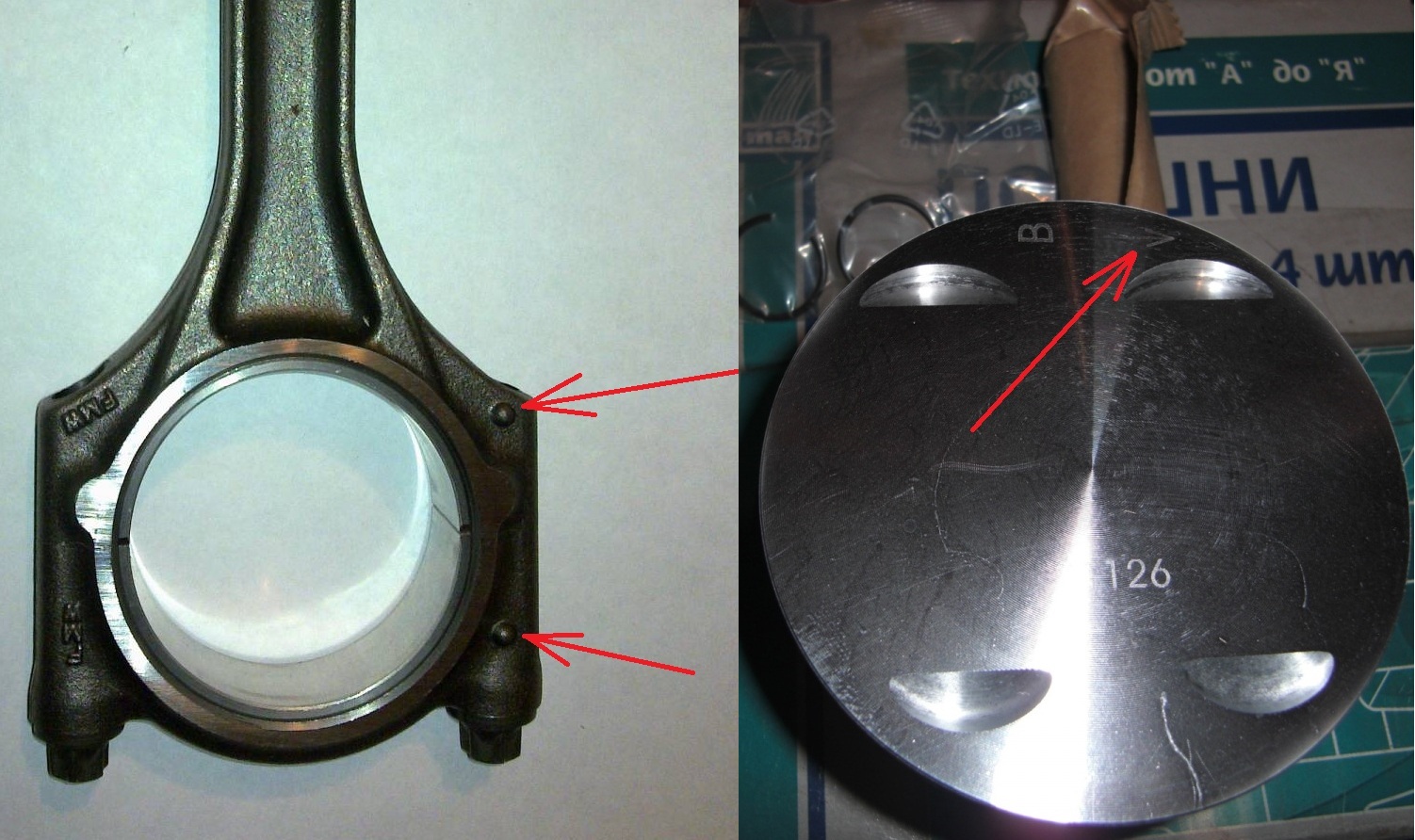
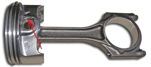
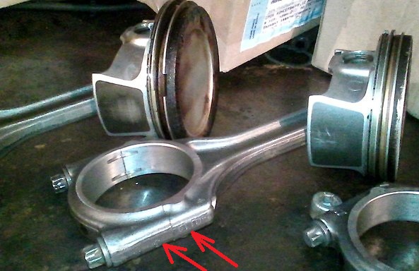
16. Insert the connecting rod into the piston in accordance with the previously made marks so that the mark on the connecting rod faces the front of the piston (the arrow is directed to this side, knocked out on top of the piston bottom). Lubricate the piston pin with engine oil and insert it into the piston and connecting rod.
17. Establish lock rings on both parties of a piston pin. At the same time, pay attention to the fact that the piston rings must be clearly installed in the piston grooves.
Note:
A piston ring that is not clearly fixed in the piston groove will pop out of it when the engine is running and cause accidental damage.
18. Install the oil scraper ring expander on the piston.
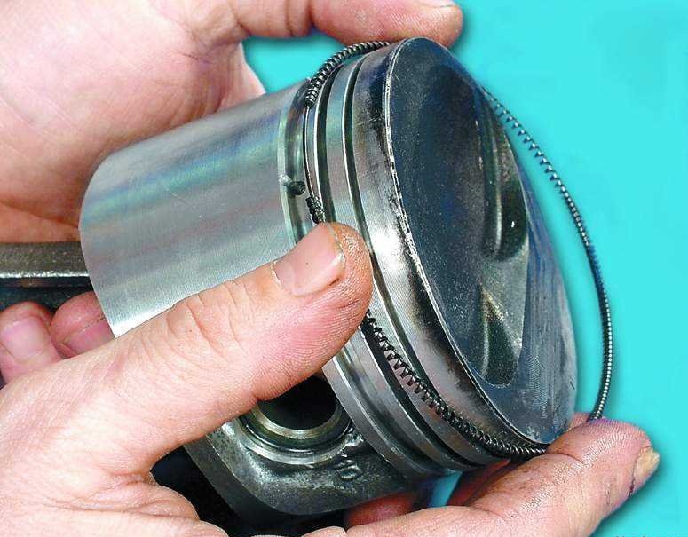
19. Install piston rings. This work is recommended to be done with a special puller. If it is not there, install the piston and oil scraper rings on the piston, carefully spreading the ring locks.
Notes:
The order of installation of piston and oil scraper rings: the oil scraper ring A is installed first (the lock of the ring must be on the opposite side of the expansion spring lock), then the lower compression ring B, the last - the upper compression ring C.
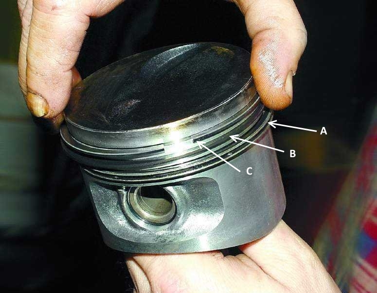
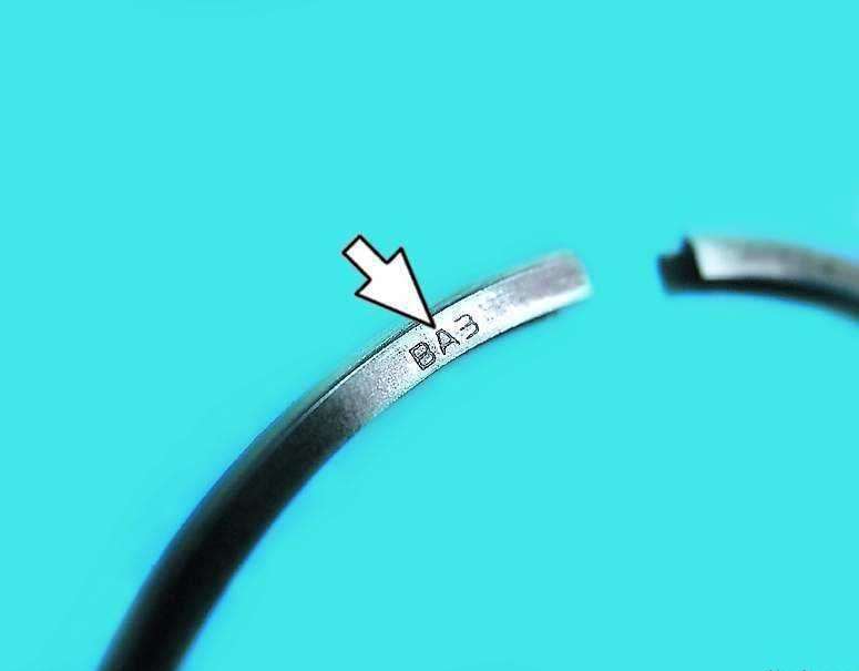
At the same time, please note that the inscription “VAZ”, “TOP” or “TOP” can be embossed on the rings. With this inscription, the rings are installed upwards (towards the piston crown). If there is no inscription, the oil scraper and top compression can be installed in any position.
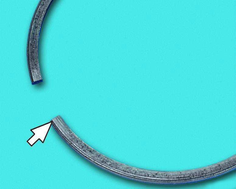
The lower compression ring differs from the upper one except for the thickness by the presence of a groove and is installed with this groove down.
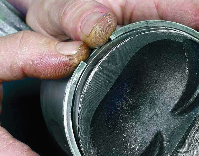
20. Turn the piston rings in the piston grooves to make sure they turn easily. If any ring does not turn or sticks, it must be replaced.
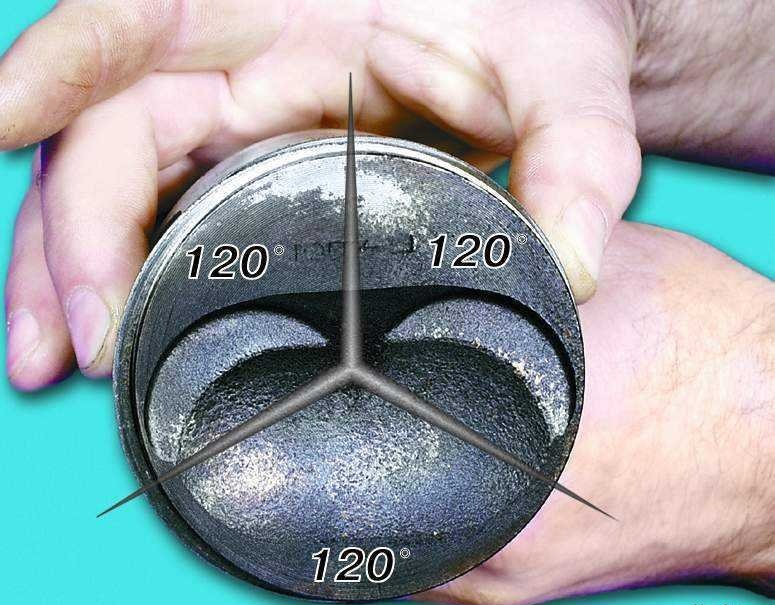
21. Turn the piston rings on the piston so that their locks are located at an angle of 120 ° to each other.
22. Thoroughly wipe the connecting rod journals of the crankshaft with a clean cloth.
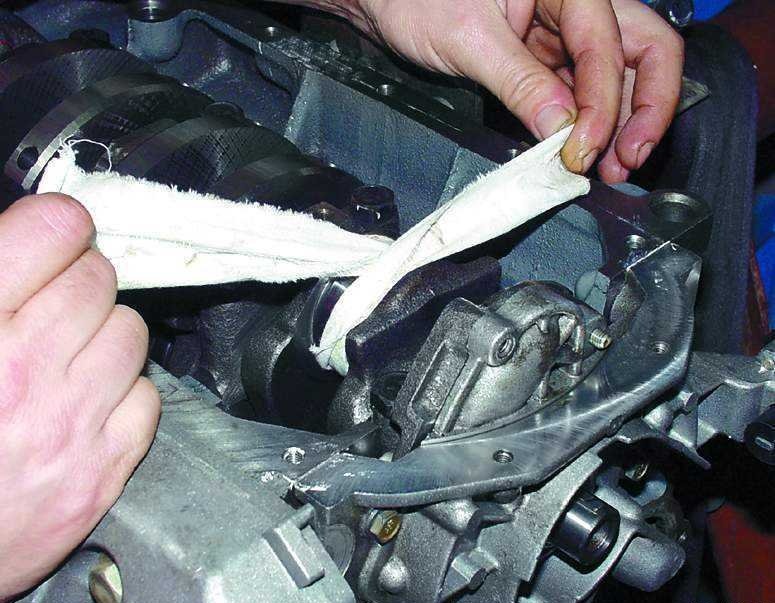
23. Thoroughly wipe the cylinder mirrors with a clean cloth and lubricate them with engine oil.
24. Insert the liner into the connecting rod in accordance with the previously made marks so that the insert antenna enters the groove in the connecting rod (similarly, as in paragraph 9 of the article). Then lubricate the liner and piston with engine oil.
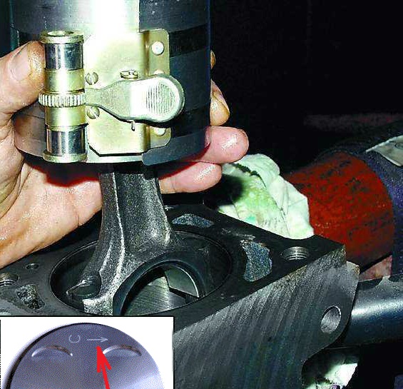
25. Put on the piston a special mandrel for compressing the piston rings and carefully lower the connecting rod into the cylinder.
Note:
It is recommended to pre-turn the crankshaft so that its connecting rod journal, on which the connecting rod and piston group is mounted, is installed at BDC. The arrow on the piston crown must point towards the front of the engine (toward the camshaft drive).
26. Firmly press the mandrel against the block and use the hammer handle to push the piston into the cylinder.
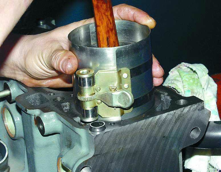
Note:
If the mandrel does not fit snugly against the cylinder block, piston rings can be broken.
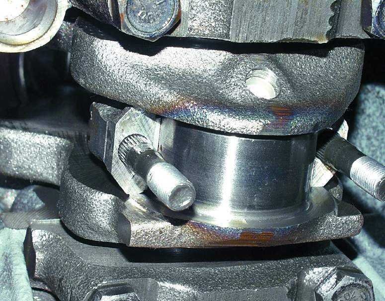
27. Establish the lower head of a rod on a neck of a cranked shaft.
28. Insert the liner into the connecting rod cap in accordance with the previously made marks so that the insert tip fits into the groove in the connecting rod cap. Then lubricate the bearing with engine oil.
29. Install the connecting rod cap. The connecting rod marking on the cap and the bottom head of the connecting rod must be on the same side.
30. Screw in bolts of its fastening and tighten them the demanded moment . Install the rest of the pistons in the same way.
31. Install the oil receiver and screw in the three bolts of its fastening.
32. Apply anaerobic threadlocker to the flywheel mounting bolts. Install the flywheel , lock plate and screw the flywheel mounting bolts.
33. For ease of installation, apply a thin layer of grease to the surface of the cylinder block and “glue” the oil pan gasket to it.
34. Establish the pallet of an oil crankcase and screw in bolts of its fastening.
35. Next, assemble the engine in reverse order .
Note:
The installation of the cylinder head is described here and here , the camshaft drive belt - here and here (depending on the type of engine).
The article is missing:
- Tool photo
- Photo of parts and consumables
Source: carpedia.club