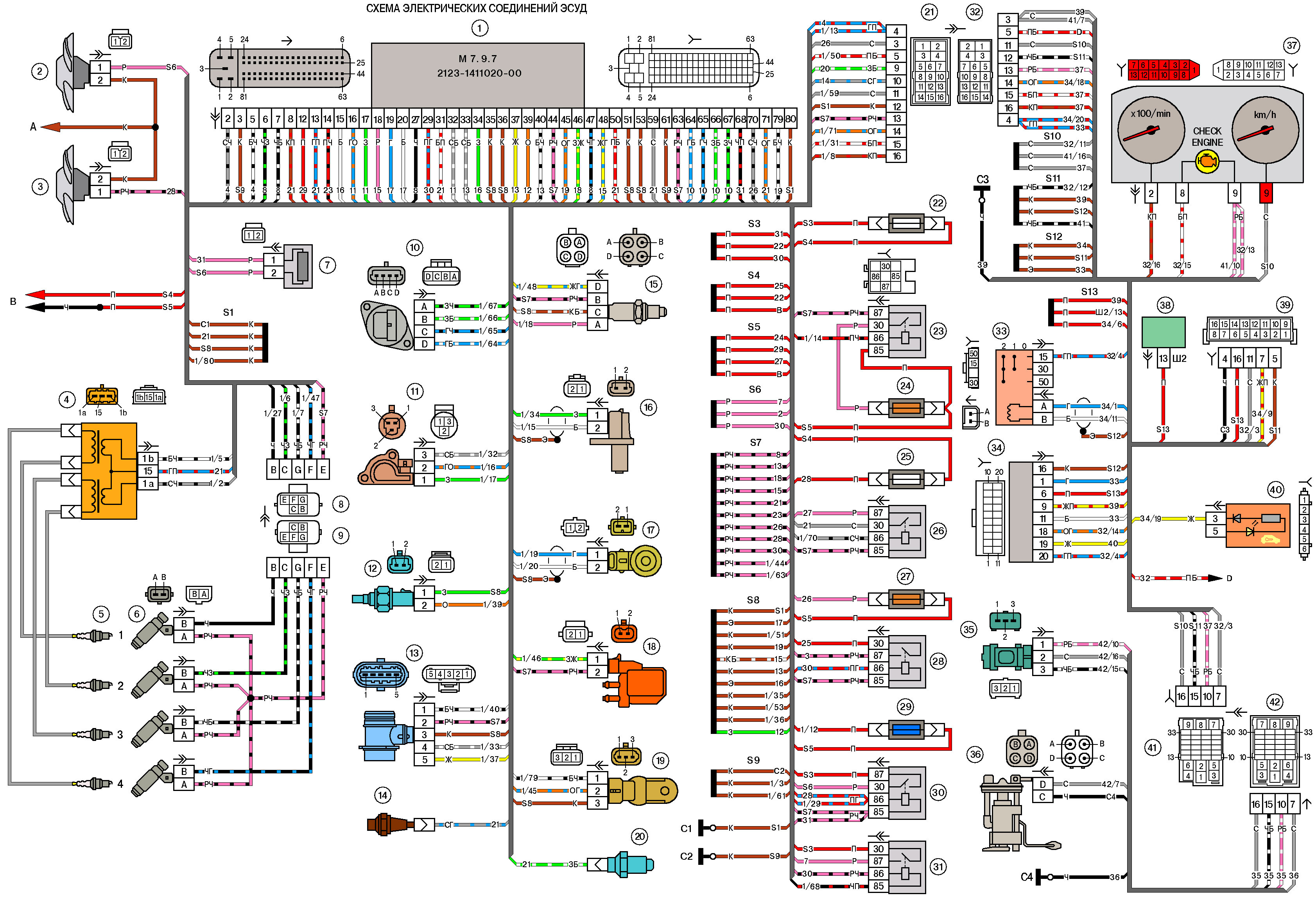
- 1 – controller;
2 - electric fan of the engine cooling system, right;
3 - electric fan of the engine cooling system, left;
4 - ignition module;
5 - spark plugs;
6 - nozzles;
7 - resistor;
8 – a block of a plait of system of ignition to a plait of atomizers;
9 - block of the injector harness to the ignition system harness;
10 - idle speed regulator;
11 - throttle position sensor;
12 - coolant temperature sensor;
13 - mass air flow sensor;
14 - oil pressure warning lamp sensor;
15 – oxygen sensor;
16 - crankshaft position sensor;
17 - knock sensor;
18 - solenoid valve for adsorber purge;
19 - phase sensor;
20 - coolant temperature indicator sensor;
21 - block of the ignition system harness to the instrument panel harness;
22 - fuse for the power supply circuit of the right electric fan;
23 - ignition relay;
24 - ignition relay fuse;
25 - fuse for the power supply circuit of the left electric fan;
26 - relay of the electric fuel pump;
27 - fuse for the power supply circuit of the electric fuel pump;
28 - left electric fan relay;
29 - controller power circuit fuse;
30 - right electric fan relay;
31 - additional relay;
32 – a block of a plait of the panel of devices to a plait of system of ignition;
33 - ignition switch;
34 - automobile anti-theft system;
35 - vehicle speed sensor;
36 - electric fuel pump;
37 - instrument cluster;
38 - mounting block;
39 - diagnostic block;
40 - a block of control lamps;
41 - block of the instrument panel harness to the rear harness;
42 - rear harness block to the instrument panel harness. - A - to the "minus" terminal of the battery;
B - to the "plus" terminal of the battery;
C1, C2 - grounding points for the ignition system harness;
C3 - grounding point of the instrument panel harness;
C4 - grounding point of the rear harness;
D - to contact "86" of the additional starter relay.
S2 - absent.
Ignition system harness - 2123-3724026-30
Instrument panel harness - 2123-3724030-20
The wires in this diagram have a letter designation
of color and a designation of the number of the circuit element to which
this wire is connected. Through the fraction indicates
the contact number of the block.
Source http://kipdoc.ru/elektroshemy-vaz/211-elektricheskaya-shema-niva-shevrole-ebu-mp-70.html
Replacement of hydraulic bearings of Chevrolet Niva valve drive levers
1 to 3 hours
[[ article.getBookmarkIcon() ]]
Instrument
Chevrolet Niva Rear Brake Hose Replacement
1 to 3 hours
[[ article.getBookmarkIcon() ]]
Pit / Flyover
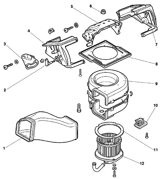
Removal and installation of the heater fan electric motor Chevrolet Niva
3 - 6 hours
[[ article.getBookmarkIcon() ]]
Instrument
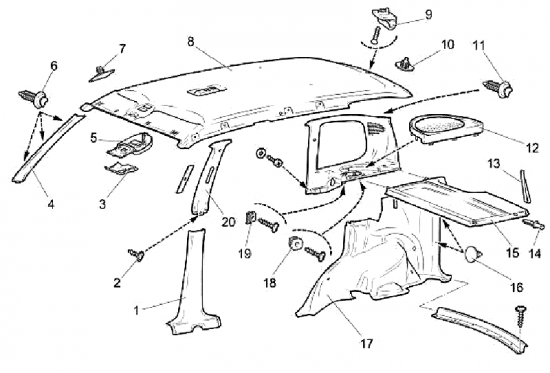
Removal and installation of facings of salon Chevrolet Niva
[[ article.getBookmarkIcon() ]]
Instrument
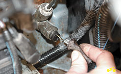
Replacement of the gauge of a signal lamp of an emergency drop in pressure of oil Chevrolet Niva
[[ article.getBookmarkIcon() ]]
Instrument
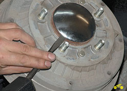
Removal and installation of a brake drum Chevrolet Niva
1 to 3 hours
[[ article.getBookmarkIcon() ]]
lift
Removal and installation of an intermediate shaft Chevrolet Niva
1 to 3 hours
[[ article.getBookmarkIcon() ]]
Pit / Flyover
![1 generation [restyling] [2009 - 2017]](/uploads/Chevrolet_Niva_2002-2009_.jpg)
