![1 generation [restyling] [2009 - 2017]](/uploads/Chevrolet_Niva_2002-2009_.jpg)

-
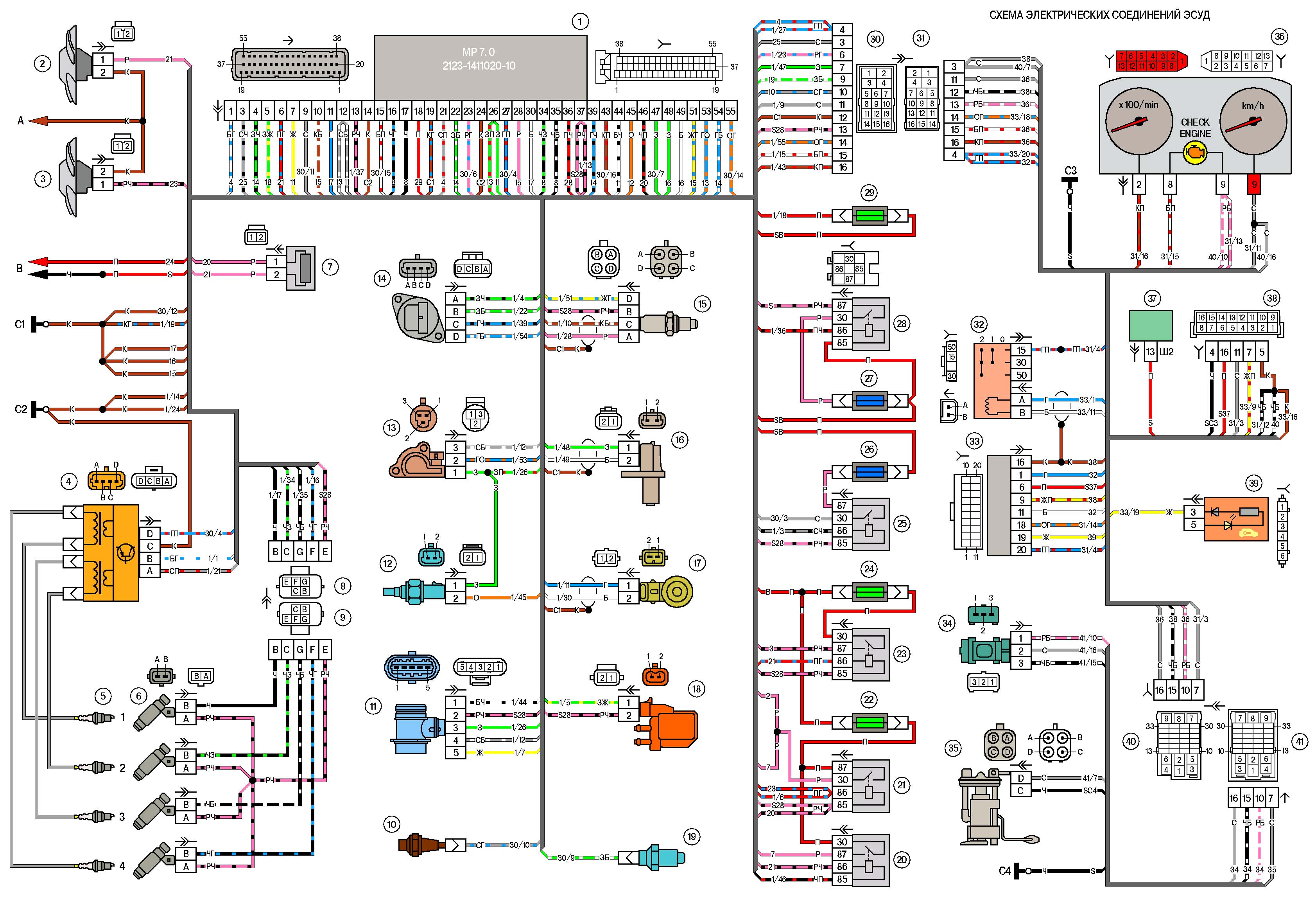
1 – controller;
2 - electric fan of the engine cooling system, right;
3 - electric fan of the engine cooling system, left;
4 - ignition module;
5 - spark plugs;
6 - nozzles;
7 - resistor;
8 – a block of a plait of system of ignition to a plait of atomizers;
9 - block of the injector harness to the ignition system harness;
10 – the gauge of a control lamp of pressure of oil;
11 - mass air flow sensor;
12 - coolant temperature sensor;
13 - throttle position sensor;
14 - idle speed regulator;
15 – oxygen sensor;
16 - crankshaft position sensor;
17 - knock sensor;
18 - solenoid valve for adsorber purge;
19 - coolant temperature indicator sensor;
20 - additional relay;
21 - right electric fan relay;
22 - fuse for the power supply circuit of the right electric fan;
23 - left electric fan relay;
24 - fuse for the power supply circuit of the left electric fan;
25 - electric fuel pump relay;
26 - fuse for the power supply circuit of the electric fuel pump;
27 - ignition relay fuse;
28 - ignition relay;
29 - controller power circuit fuse;
30 – a block of a plait of system of ignition to a plait of the panel of devices;
31 – a block of a plait of the panel of devices to a plait of system of ignition;
32 - ignition switch;
33 - car anti-theft system;
34 - vehicle speed sensor;
35 - electric fuel pump;
36 – a combination of devices;
37 - mounting block;
38 - diagnostic block;
39 - a block of control lamps;
40 - block of the instrument panel harness to the rear harness;
41 - block of the rear harness to the instrument panel harness;A - to the "minus" terminal of the battery;
B - to the "plus" terminal of the battery;
C1, C2 - grounding points for the ignition system harness;
C3 - grounding point of the instrument panel harness;
C4 - grounding point of the rear harness.
The wires in this diagram have a letter designation
of color and a designation of the number of the circuit element to which
this wire is connected. Through the fraction indicates
the contact number of the block. The symbol "S28" or
"SB" means that the wire is connected to the circuit element
numbered 28 or marked with the letter B through a dot -
Source http://kipdoc.ru/elektroshemy-vaz/211-elektricheskaya-shema-niva-shevrole-ebu-mp-70.html