![1 generation [2003 - 2007]](/uploads/Mitsubishi_Outlander_I_2003_-_2008_.jpg)
![3 generation [2012 - 2014]](/uploads/3.png)
![XL [2005 - 2012]](/uploads/4d137205da66f_.jpg)

Tools:
- Ratchet wrench
- socket extension
- socket head 10 mm
- socket head 13 mm
- 19 mm socket (for 6B31 engine)
- 36mm socket (for 6B31 engine)
- Torx socket (sprocket) T20
- Hex bit head 6 mm (for 4B11/4B12 engines)
- torque wrench
- Open-end wrench 10 mm
- Box wrench curved 8 mm
- Coolant change tool (MB991871)
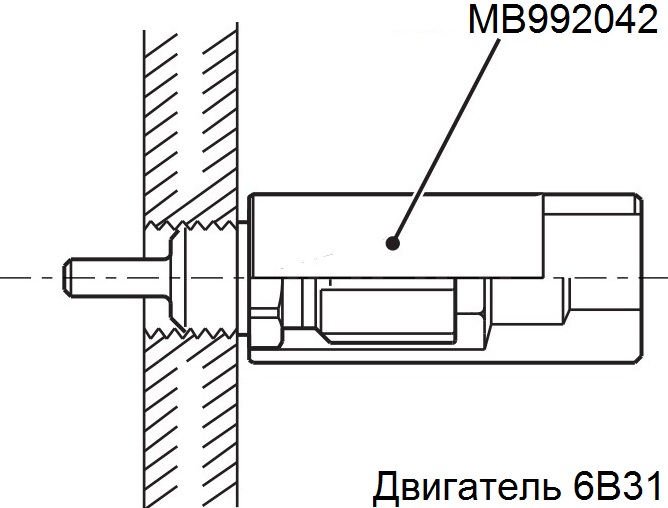
- Special tool for removing the coolant temperature sensor MB992042
- Screwdriver flat medium
- Phillips screwdriver, medium
- Pliers
- Curved round nose pliers
- Funnel
- Knife (or scraper)
- multimeter
- Thermometer (for water)
- Marker
Parts and consumables:
- Thermostat housing (1305A169/1305A091 - for 4B11 and 4B12 engines, 1305A174/1305A219/1305A293 - for 6B31 engine; if required)
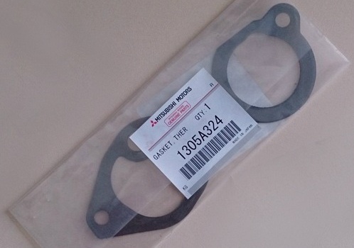
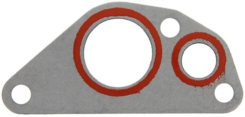
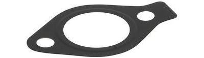
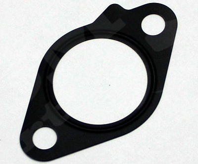
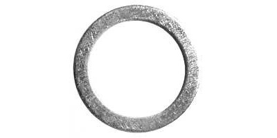
- Thermostat housing gasket (1305A092/1305A324 for 4B11 and 4B12 engines, 1305A084 and MD194919 for 6B31 engine)
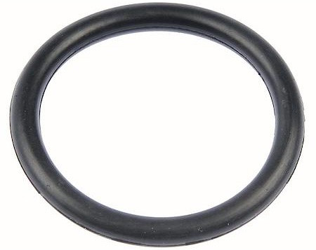
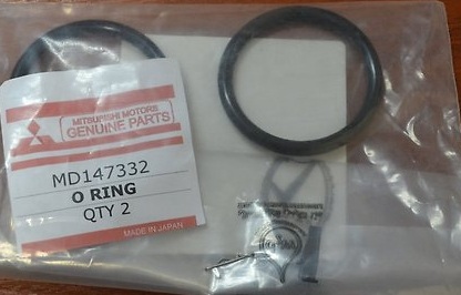
- O-ring (MD030764 - for 4B11 and 4B12 engines, MD147332 - 2 pcs. - for 6B31 engine)
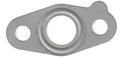
- Sealing gasket MN187969/1305A286 (for 4B11 and 4B12 engines)
- Gasket 1582A018 (for 4B11 and 4B12 engines)
- Sealing gasket MD149764 (for 4B11 and 4B12 engines)
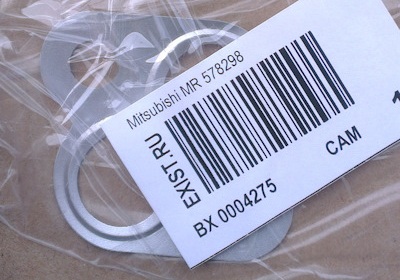
- Sealing gasket MR578298 (for 6B31 engine)
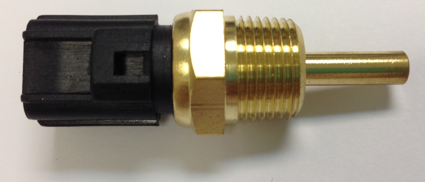
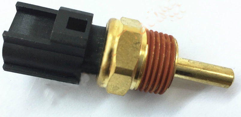
- Coolant temperature sensor MD177572 (if required)
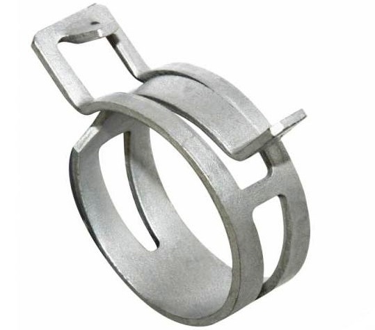
- Clamp MR993229 - 2 pcs. (release from 03.2009)
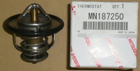
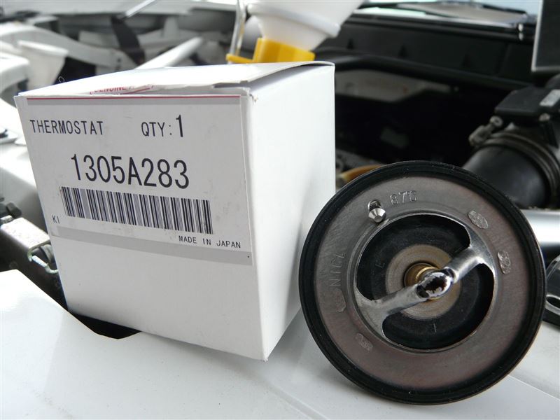
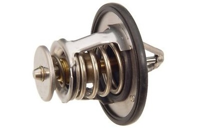
- Thermostat assembly with o-ring (MN187250 (82°C) / 1305A283 (87°C) - for 4B12 and 4B11 engines and MD194988 - for 6B31 engine, if necessary)
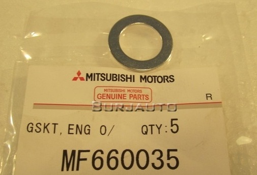
- Cylinder block drain plug seal MF660035 (4B11 and 4B12 engines)

- Cylinder block drain plug seal MF660034 and MF660042 (6B31 engine)
- Air filter element replacement (1500A190 (06-07.2009 issue)/1500A023, if required)
- Car pistons MB345544 - 2 pcs. (if necessary)
- Technical capacity
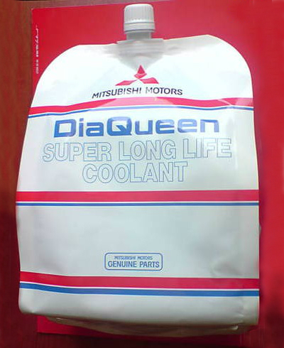
- Coolant
- Cooling system flush (if required)
- Distilled water
- Parts cleaner (degreaser)
- Steel rod (length 90-100 mm) with threaded M8 at one end (thread length 20 mm) - 2 pcs. (for 6B31 engine)
- Vessel with water
- Three bond sealant 1324N (or equivalent)
- rags
Note:
Remove the thermostat housing when replacing it or repairing the engine to gain access to the rear of the engine.
When disassembling, install clean rag plugs in the hoses/channels in the cylinder head to prevent dust and other unwanted materials from entering the cooling system.
1. Drain engine coolant as described in this article .
2. Remove the decorative engine cover as described here .

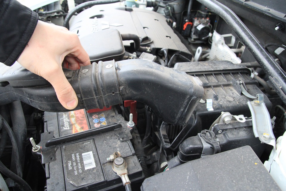
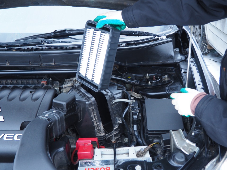
3. Remove the air filter, air duct and air inlet hose as described in this article .
4.1. (models before 02.2009) Mark the relative position of the radiator hose and clamp, then release the clamp and disconnect the lower radiator hose from the thermostat cover fitting.
Note:
After disconnecting the radiator hose, plug the hole in the hose with a plug/clean cloth to prevent dust or foreign particles from entering it.
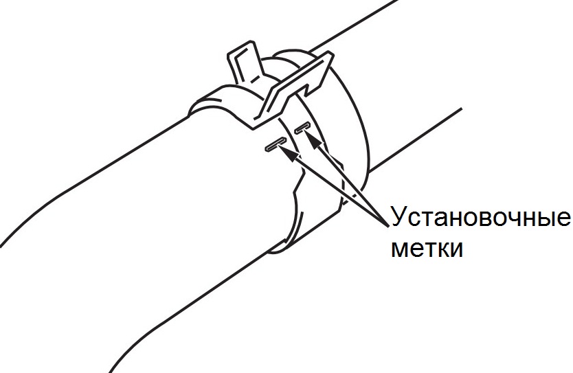
4.2.1. (Models since 03.2009) Mark the relative position of the radiator hose and clamp as shown in the illustration.
Note:
Application of installation marks is necessary for the correct subsequent installation of a new clamp.
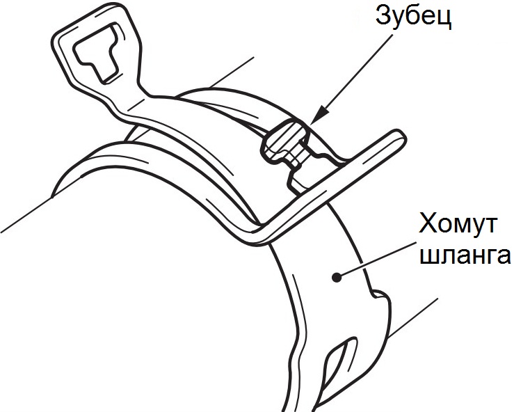
4.2.2. (models from 03.2009) Break off the tooth of the hose clamp, then release the clamp and disconnect the lower radiator hose from the thermostat cover fitting.
Note:
If you do not break off the tooth of the hose clamp, then it will not be possible to open the clamp.
After disconnecting the radiator hose, plug the hole in the hose with a plug/clean cloth to prevent dust or foreign particles from entering it.
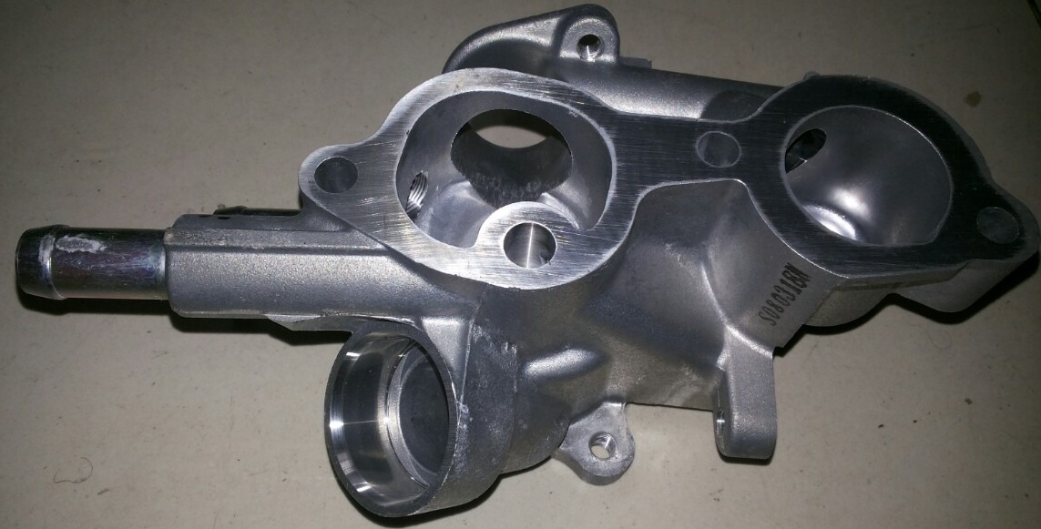
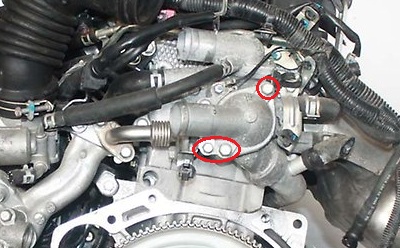
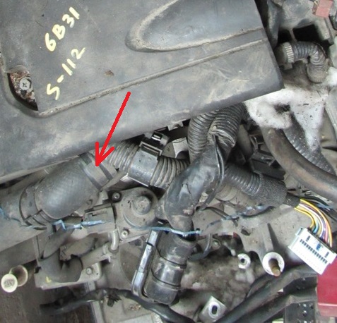
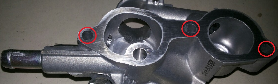
5. Remove the three mounting bolts and remove the thermostat cover (for clarity, the location of the bolts is shown on the removed engine, the first two photos below are the 4B12 engine, the third one is 6B31). On the 4B11/4B12 engine, the third bolt secures the harness retainer connection.
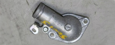
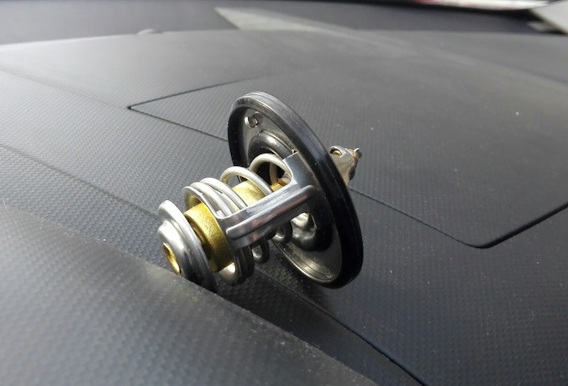
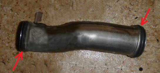
6. Remove the Outlander HL thermostat assembly with the O-ring.
7.1. (engines 4B11 and 4B12) In the same way as for removing the lower radiator hose, disconnect the upper hose from the outlet pipe of the cooling system.
Note:
After disconnecting the radiator hose, plug the hole in the hose with a plug/clean cloth to prevent dust or foreign particles from entering it.
7.2. (engine 6B31) Similar to the work on removing the lower radiator hose, disconnect the upper hose from the outlet pipe of the thermostat housing.
Note:
After disconnecting the radiator hose, plug the hole in the hose with a plug/clean cloth to prevent dust or foreign particles from entering it.
8.1. (engines 4B11 and 4B12) Then disconnect the coolant inlet hose (to the throttle body) from the coolant outlet pipe by opening the clamp and sliding it along the hose.
8.2. (engine 6B31) Then disconnect the coolant inlet and outlet hoses (to the throttle body) from the thermostat housing nozzles by opening the clamps and sliding them along the hoses.
9. (engines 4B11 and 4B12) Remove the outlet pipe of the cooling system together with the seal by unscrewing the two bolts of its fastening to the thermostat housing.
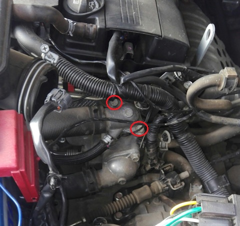
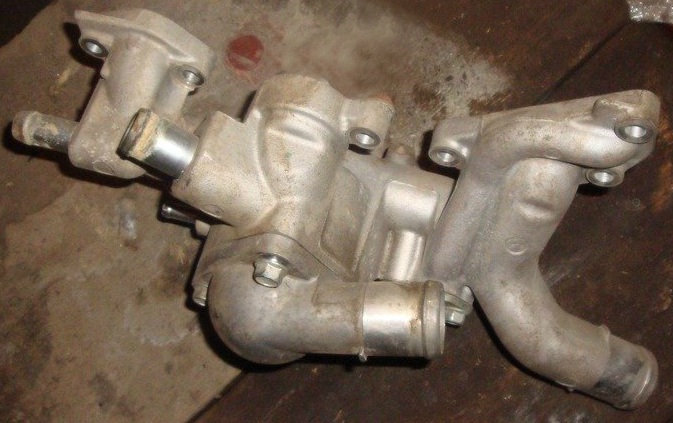
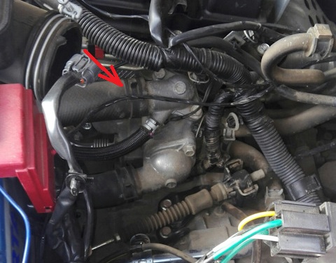
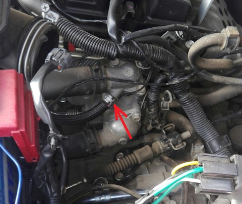
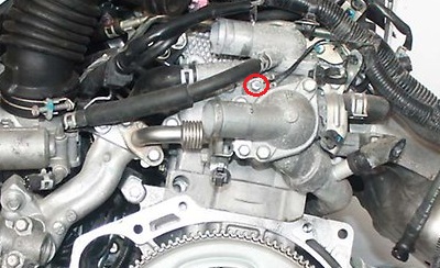
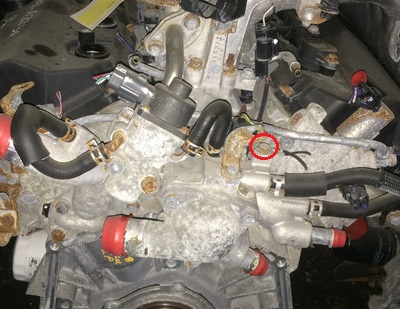
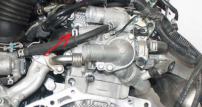
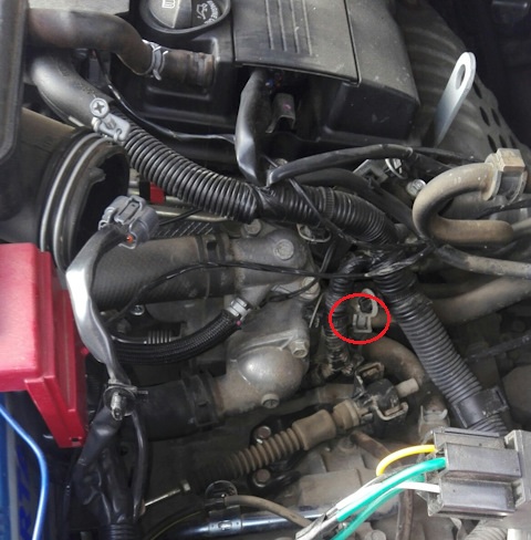
10. Disconnect the block of wires from the connector of the coolant temperature sensor (the location of the block of wires is shown for clarity on the removed engine, the first photo is the 4B12 engine, the second is 6B31).
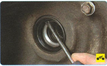
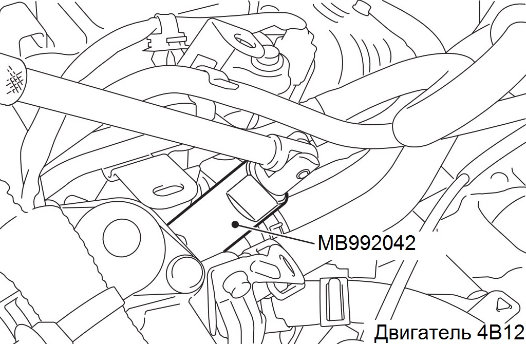
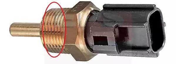
11. Remove the coolant temperature sensor using the special tool (tool head, catalog number MB992042).
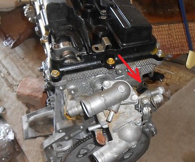
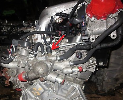
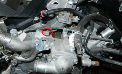
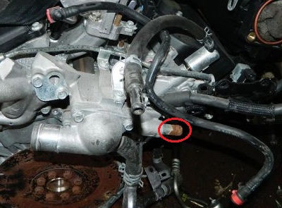
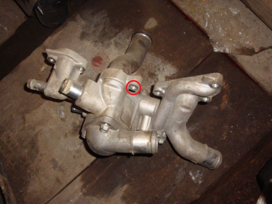
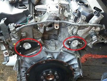
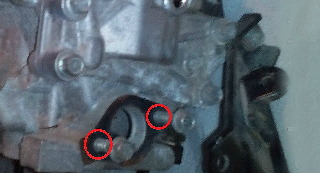
12. Unscrew the ground wire mounting bolt and remove it from the thermostat housing (the location of the ground wire mounting bolt is shown on the removed engine for clarity, the first photo is the 4B12 engine, the second is 6B31).
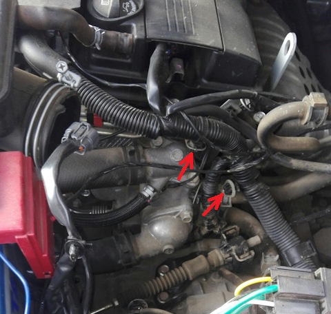
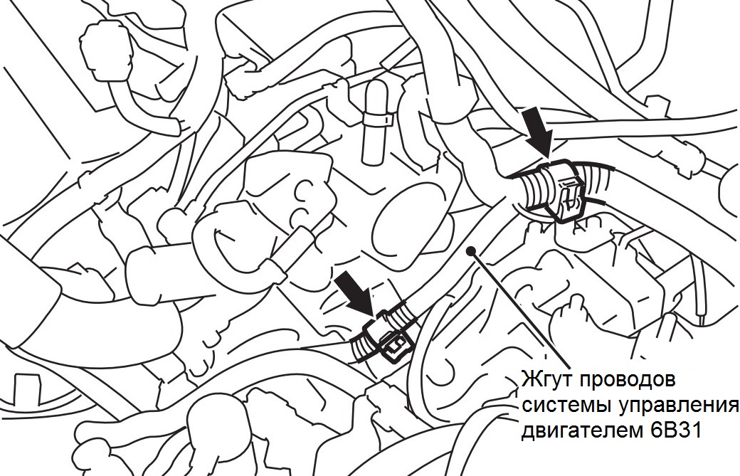
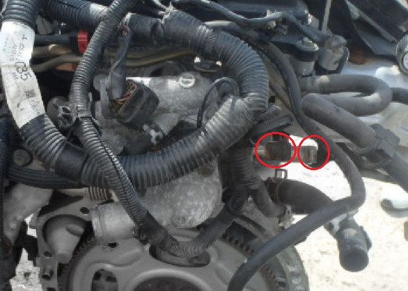
13. Using curved pliers, disconnect the clamps of the wiring harness of the engine control system and take the wires away from the thermostat housing (in the first photo - the 4B12 engine, in the second - 6B31).
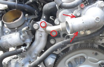
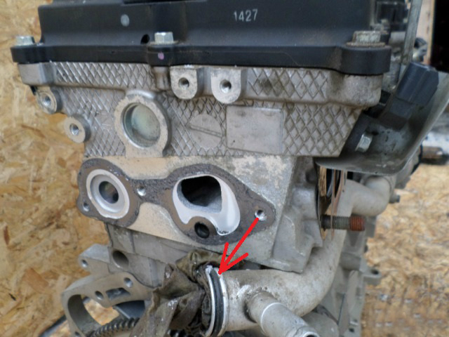
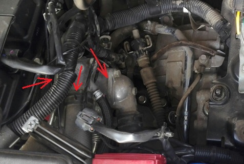
14.1. (engines 4B11 and 4B12) Then unscrew the four bolts securing the tube of the exhaust gas recirculation valve and remove it together with the gaskets (two bolts are not visible in the photo, their location is indicated by arrows).
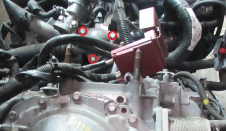
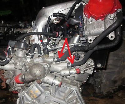
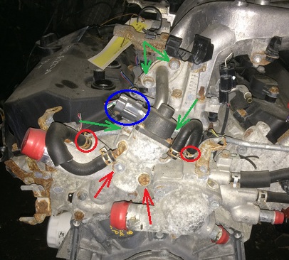
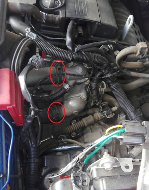
14.2.1. (engine 6V31, production before 05.2009) Disconnect the wiring harness from the EGR valve connector (blue oval in the photo below), remove the valve cooling hoses from the thermostat housing nozzles by opening the clamps and sliding them along the hoses (red ovals). Also unscrew the EGR valve mounting bolts (red arrows in the photo below), four tube mounting bolts (green arrows in the photo below) of the exhaust gas recirculation system valve and remove the valve with hoses and tube together with gaskets.
14.2.2. (Engine 6V31, release from 07.2010) Unscrew the two mounting bolts and remove the thermostat housing cover together with its sealing gasket.
Note:
The placement of the bolts is the same as in the photo above (in paragraph 14.2.1). Instead of the EGR valve, which was installed on earlier models, a cover with the same gasket is installed here.
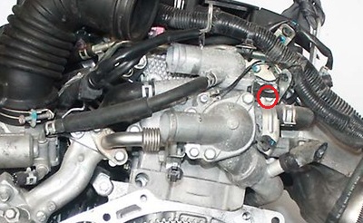
15. Disconnect the cooling system hose from the thermostat housing by opening the clamp and sliding it along the hose (for clarity, the location of the clamp is shown on the removed engine, the first photo is the 4B12 engine, the second is 6B31).
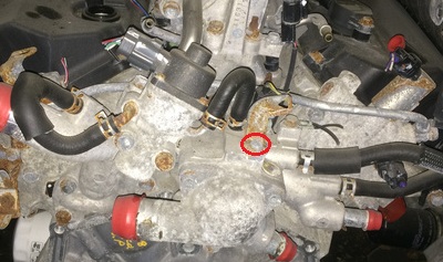
16. Then unscrew the bolt shown in the photo below and remove the wiring harness bracket from the thermostat housing (for clarity, the location of the bracket mounting bolt is shown on the removed engine, the first photo is the 4B12 engine, the second is 6B31).
17.1. (Engines 4B11 and 4B12) Disconnect from the nozzles of the thermostat housing by opening the clamps, two hoses of the interior heater.
17.2. (Engine 6B31) Disconnect from the nozzle of the thermostat housing, by opening the clamp, the interior heater hose (for clarity, shown on the removed engine).
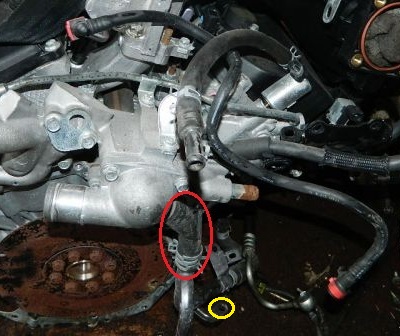
18. (engine 6B31) Unscrew the bolt (marked with a yellow oval in the photo below) fastening the automatic transmission fluid cooling return line hose (complete with the hose from the interior heater) and disconnect this hose (marked with a red oval in the photo below) from the nozzle of the thermostat housing, unclenching the clamp and sliding it along the hose.
19.1. (engines 4V11 and 4V12) Now unscrew the three remaining bolts securing the thermostat housing and remove it together with the gasket (the location of the bolts is shown on the removed thermostat housing).
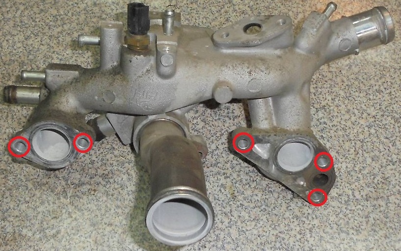
19.2. (engine 6V31) Unscrew the five bolts securing the thermostat housing and remove it together with the gaskets and the inlet pipe (the location of the bolts is shown on the removed thermostat housing).
20. (Engine 6B31) Remove the bolt securing the supply pipe to the thermostat housing.
21. Remove the O-ring (engines 4V11 and 4V12) / O-rings (engine 6V31) of the supply pipe of the cooling system.
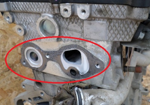
22. Clean the mating surface of the cylinder block from gasket residues and deposits and degrease so that the connection between the thermostat housing and the block head through the gasket is of high quality (the first photo below is the 4B12 engine, the second photo is 6B31).
23. Check the removed parts for damage/cracks, etc.
Note:
If necessary, replace defective parts. The thermostat housing is always replaced with new gaskets.
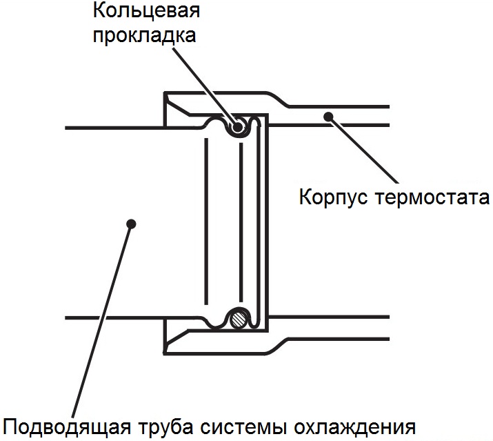
24. Install the O-ring(s) in the groove(s) in the coolant supply pipe.
Note:
Use only new O-ring(s) to avoid leaks.
25. Apply some coolant or water to the outer surface of the O-ring, as well as to the inner surface of the thermostat housing that comes into contact with the O-ring during installation.
Note:
Applying coolant or water will simplify the operation of connecting the pipe to the thermostat housing.
Keep engine oil and grease away from the O-ring surface.
Do not allow sand, dust, etc. to enter the connection points of the supply pipe of the cooling system.
26. (engine 6B31) Install the exhaust pipe in the thermostat housing of the engine 6B31 and fix the connection with a bolt with a torque of 23 ± 6 Nm.
27.1. (engines 4B11 and 4B12) Install a new gasket and thermostat housing, tightening the mounting bolts to rated torque.
Note:
The tightening torque of the thermostat housing bolts is 24 ± 3 Nm.
27.2.1. (engine 6B31) Screw two steel rods 90-100 mm long with cut M8 threads at one end (thread length 20 mm) into the holes of the right cylinder head.
27.2.2. (6B31 engine) Install the appropriate thermostat housing gasket on the rods. Then install the second gasket on the left block head and thermostat housing. Install the five bolts of the thermostat housing in turn, unscrewing the installed rods in the course of work. Tighten the thermostat housing bolts to the specified torque.
Note:
The tightening torque of the thermostat housing bolts is 23 ± 6 Nm.
28. Check the coolant temperature sensor as described here .
29. Clear a carving of the gauge of temperature of a cooling liquid if the old gauge is established.
30. Apply the specified sealant to the sensor threads as shown.
Note:
Sealant - Three bond 1324N or equivalent.
Install the sensor as soon as possible after applying the sealant (within 3 to 5 minutes).
After installing the sensor, wait at least an hour before adding coolant.
31. Install and tighten the transducer to the specified nominal torque.
Note:
Tightening torque - 30 ± 9 Nm.
Similar to the removal procedure, tighten the coolant temperature sensor using the special tool (tool head MB992042).
32.1. (engines 4B11 and 4B12) Install the EGR valve tube with new gaskets, tightening the mounting bolts to the specified torque.
Note:
The nominal tightening torque of the bolts is 20 ± 2 Nm.
32.2.1. (engine 6B31, production before 05.2009) Install the EGR valve tube and valve with new gaskets, tightening the fastening bolts to the nominal torque.
Note:
The nominal tightening torque of the EGR valve fastener bolts is 23 ± 6 Nm.
The nominal tightening torque of the bolts of the fastener of the tube of the exhaust gas recirculation system is 20 ± 5 Nm.
32.2.2. (engine 6B31, production from 07.2010) Install the thermostat cover on the housing, tightening the bolts of its fastening to a torque of 23 ± 6 Nm.
33. Connect, in the reverse order of removal, the hoses of the interior heater (and automatic transmission return line circuit, engine 6B31), cooling system and throttle valve to the thermostat housing.
Note:
Tighten the automatic transmission fluid cooling return hose bolt to 23 ± 3 Nm.
34. Connect the harness bracket and the ground wire to the thermostat housing by tightening their fastening bolts to 11 ± 1 Nm and 5 ± 1 Nm respectively.
35. Reinstall the wire harness retainer removed in step 13.
36. (engines 4B11 and 4B12) Install the outlet pipe of the cooling system on the thermostat housing, tightening its fastening bolts to a torque of 24 ± 3 Nm.
37. Install the thermostat assembly with O-ring and thermostat cover as described in this article (items 1-2 of the "Installation..." subsection).
38.1. Install the lower and upper radiator hoses to the thermostat cover and the cooling system outlet pipe (4V11 and 4V12 engines) / thermostat housing pipe (6B31 engine), respectively, as described below.
38.1.1. (models before 03.2009) When connecting the radiator hose, put the hose on the pipe until it stops against the projection of the pipe, then tighten the clamp.
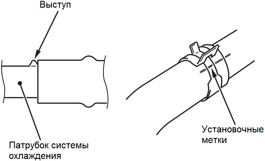
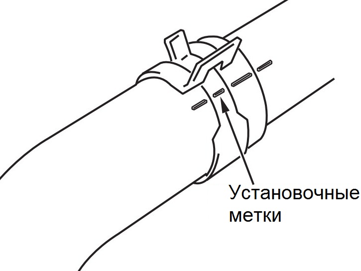
38.1.2. (Models prior to 03.2009) The hose clamp must always be installed in the position in which the clamp was previously installed. Therefore, before installing the clamp, align the alignment marks on the hose clamp and hose, then connect the hose (see figure above).
38.2.1. (Models since 03.2009) Place a match mark on the new clamp in the same place as on the old clamp removed when the hose was disconnected.
Note:
To avoid rust, do not use a hose clamp that has been removed and has a broken tooth.
38.2.2. (models from 03.2009) Install a new clamp on the radiator hose.
38.2.2. (production models from 03.2009) When connecting the radiator hose, put the hose on the socket until it stops against the ledge of the socket.
38.2.3. (models from 03.2009) Align the alignment marks on the clamp and the hose, then release the clamp tooth to compress the hose with the clamp and fix it on the nozzle.
Note:
The hose clamp should always be installed in the position it was previously installed.
39. Reinstall the remaining removed parts in the reverse order of removal.
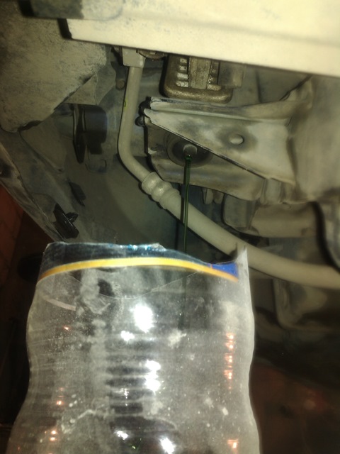
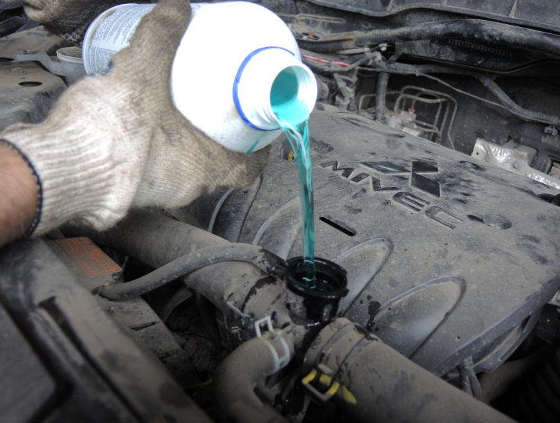
40. Fill with coolant .
41. Check for coolant leaks.
The article is missing:
- Tool photo
- Photo of parts and consumables
Source: carpedia.club