![1 generation [2003 - 2007]](/uploads/Mitsubishi_Outlander_I_2003_-_2008_.jpg)
![3 generation [2012 - 2014]](/uploads/3.png)
![XL [2005 - 2012]](/uploads/4d137205da66f_.jpg)

The main malfunctions, the elimination of which requires the removal and disassembly of the clutch:
- - increased (compared to the usual) noise when the clutch is engaged;
- - jerks during clutch operation;
- - incomplete engagement of the clutch (clutch "slips");
- - incomplete disengagement of the clutch (clutch "leads").
If the clutch fails, we recommend replacing all its elements at the same time (driven and driving discs, clutch release bearing), since replacing the clutch is laborious, and the life of undamaged clutch elements has already been reduced. If they are installed again, it may be necessary to replace the clutch again after a relatively short mileage.
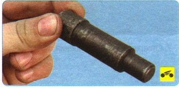
You will need: a “12” wrench (a socket head is more convenient), a large screwdriver and a mandrel for centering the driven disk. A commercially available mandrel for front-wheel drive VAZ vehicles is also suitable.
1. Remove the gearbox.
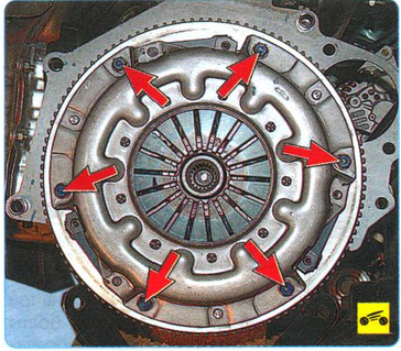
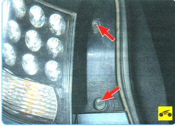
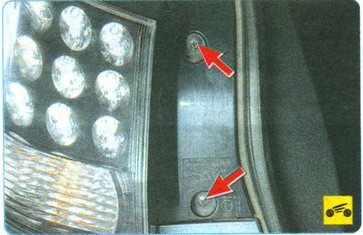
This is how the cover bolts are located.
2. If it is planned to install the old pressure plate, mark in any way (for example, with paint) the relative position of the disc casing and the flywheel in order to set the pressure plate in its original position (to maintain balance).
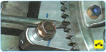
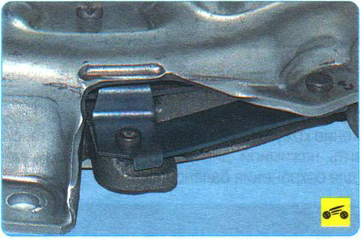
3. Holding the flywheel with a large clutch screwdriver against the engine flywheel (or a mounting spatula) from turning ...
4. ... Turn out six bolts of fastening of a casing of a pressure plate of coupling to a flywheel. Loosen the bolts evenly: each bolt one turn of the wrench, moving from bolt to bolt around the circumference.
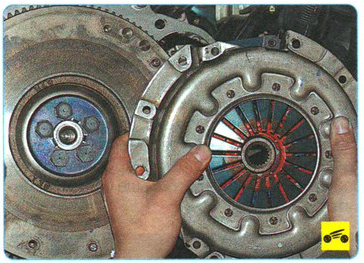
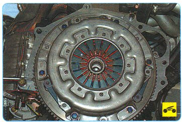
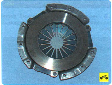
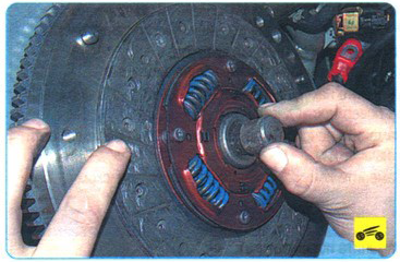
5. Remove the clutch pressure and driven discs from the flywheel while holding the driven disc.
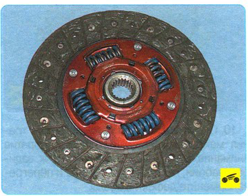
6. Examine a conducted disk of coupling. Cracks on the details of the driven disk are not allowed.
7. Check the degree of wear of the friction linings. If the rivet heads are sunk by less than 0.3 mm, the surface of the friction linings is oily, or the rivet connections are loose, then the driven disk must be replaced.
If overlays of a conducted disk are greased, check up a condition of an epiploon of a primary shaft of a transmission. It may need to be replaced.
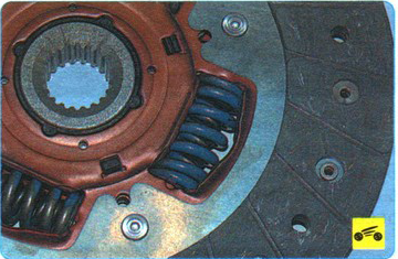
8. Check up reliability of fixing of damper springs in sockets of a nave of a conducted disk, trying to move them by hand in sockets of a nave. If the springs move easily in their seats or are broken, replace the disc.
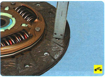
9. Check up beating of a conducted disk if during visual survey its warping is found out. If the runout is greater than 0.5 mm, replace the disc.
10. Inspect the friction surfaces of the flywheel and pressure plate, paying attention to the absence of deep scratches, scuffs, nicks, obvious signs of wear and overheating. Replace defective units.
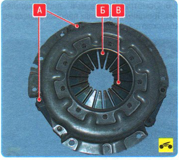
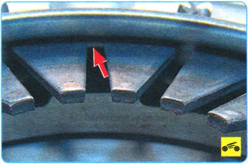
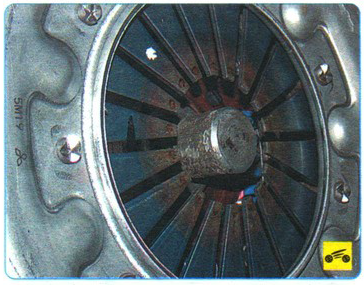
11. When loosening riveted joints A of the housing and pressure plate parts, replace the pressure plate assembly. Visually assess the condition of the disk spring B of the pressure plate. The presence of cracks on the Belleville spring is not allowed. Places B of contact between the petals of the spring and the clutch release bearing must be in the same plane and not have obvious signs of wear (wear should not exceed 0.8 mm). Otherwise, replace the pressure plate assembly.
12. Inspect the connecting links of the casing and disc. If the links are deformed or broken, replace the pressure plate assembly.
13. Estimate a condition of basic rings of a pressure spring by external survey. Rings must be free of cracks and signs of wear. Otherwise, replace the pressure plate assembly.
14. Before installing the clutch, check the ease of movement of the driven disk along the splines of the input shaft of the gearbox. If necessary, remove the causes of seizing or replace defective parts.
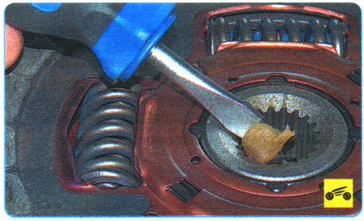
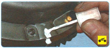
15. Apply high-melting grease to the splines of the driven disc hub.
16. When mounting the clutch, first install the driven disk using a mandrel ...
Install the driven disc so that the protruding part of the disc hub is directed towards the diaphragm spring of the clutch housing.
17. ... and then the casing of the pressure plate on the three centering pins and screw the bolts securing the casing to the flywheel. Screw the bolts evenly, one turn of the wrench each, alternately moving from bolt to bolt along the diameter. The tightening torque of the bolts is indicated in Appendix 1.
18. Remove the mandrel and install the gearbox.
19. Check and, if necessary, adjust the clutch release drive.
Source: Third Rome Publishing Manual