Good day to all! Most of our Russian Polos do not have an ESP system in the package (except for Premium packages)!
And my polo didn't have it until now either.
This system is very useful.
I have finally completed this project.
To implement it, we need:
1. 6R0 907 379 AS - ABS / ESP block.
2. 6R1 614 235 C - ABS / ESP block bracket.
3. 6Q0 959 654 D - under the steering ring with a steering angle sensor.
4. 6R0 927 117 A - ESP on / off button.
5. 4D0 971 636 - the counterpart of the button.
6. 000 979 025 E - wire for connection to the ABS / ESP unit.
7. 50282021 - sealing gum for the wire.
8. 6RU 614 739 C - brake pipe from the GTZ to the ABS / ESP block.
9. 6RU 614 740 A - brake pipe from the GTZ to the ABS / ESP block.
10. N 907 647 01 - crimp contact for wires.
11. B 000 750 M3 - brake fluid 2 liters.
Before starting work, connect the diagnostic cable and save the current coding of the ABS unit! Now let's start the integration process itself ...
Let's start with the preparation of the wiring:
- remove the steering wheel
- remove the tidy
- remove the steering column
trim
- remove it under the steering switches
- unfasten the connector under the steering switches and plug the wires there.
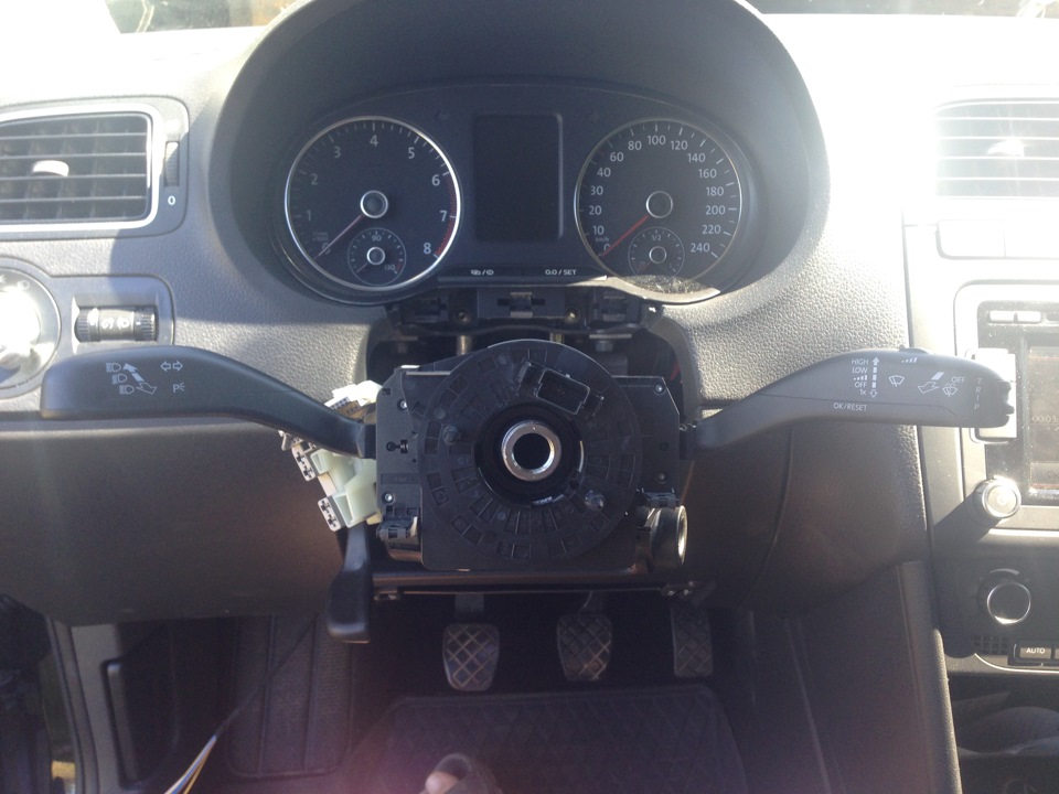
In the process of parsing.
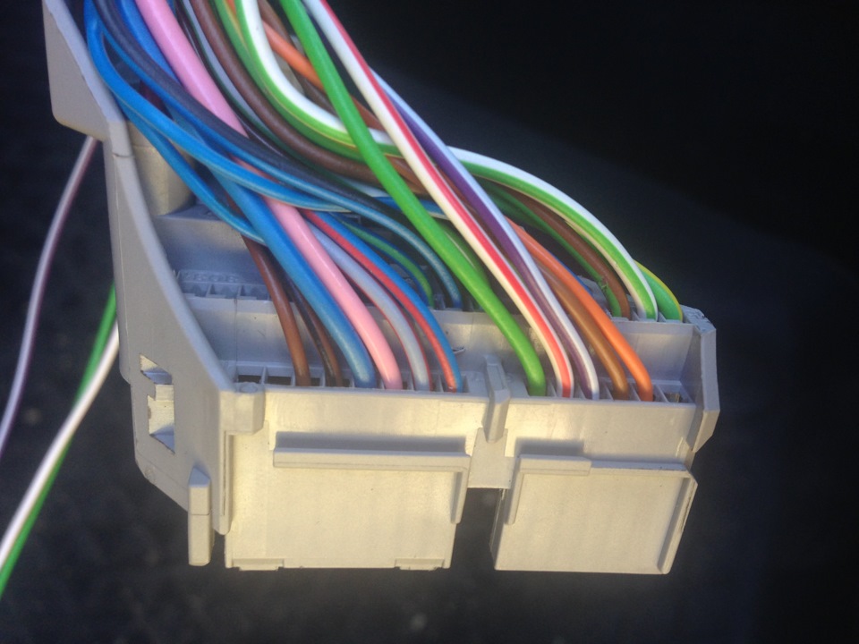
2nd pin - orange 3rd pin - brown 4th pin purple/grey 5th pin white red 6th pin green.
We pull the wires from 2,3,4 and 5 pins to the tidy wiring harness.
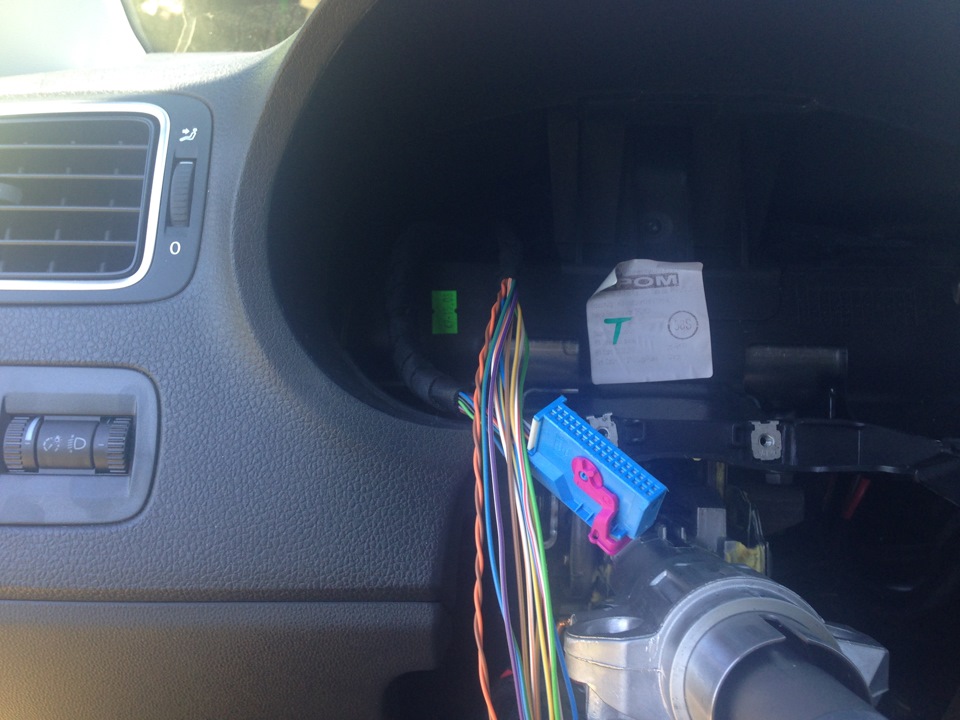
The wiring harness is brought to the tidy.
In my wiring harness, of course, there are more, since I wound the harness immediately for other special stages.
Now we unwind the wiring harness and solder:
wire from pin 2 to orange/brown wire
wire from pin 3 to orange/black wire
wire from pin 4 to brown wire
wire from pin 5 to red/yellow wire.
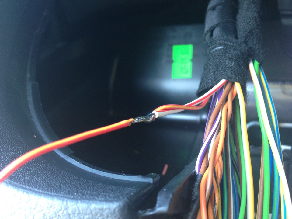
Soldered.
The wire from the 6th pin must be stretched to the fuse box (9th before). At the same time, I laid a second wire to this fuse, which will need to be brought to the ESP button.
In order to qualitatively solder to the wire from the 9th pred (black / blue), I pulled out the contact from the pred block.
- you need to move the pink contact retainer (marked with an arrow in the photo)
- insert the pinout
- pull out the contact
-
clean it - solder it
- and all this stuff is in heat shrink
- insert the contact back.
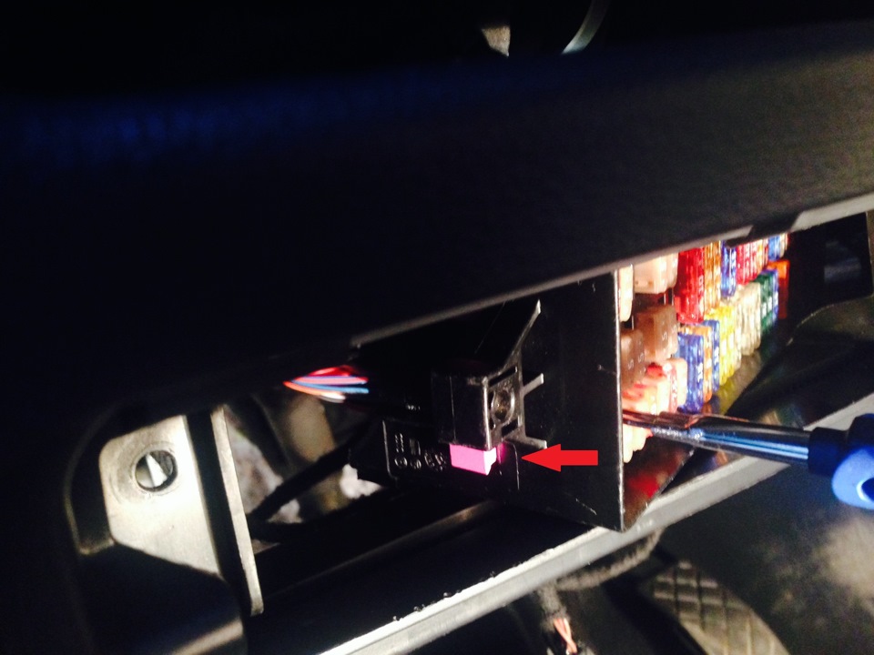
Pull out the contact.
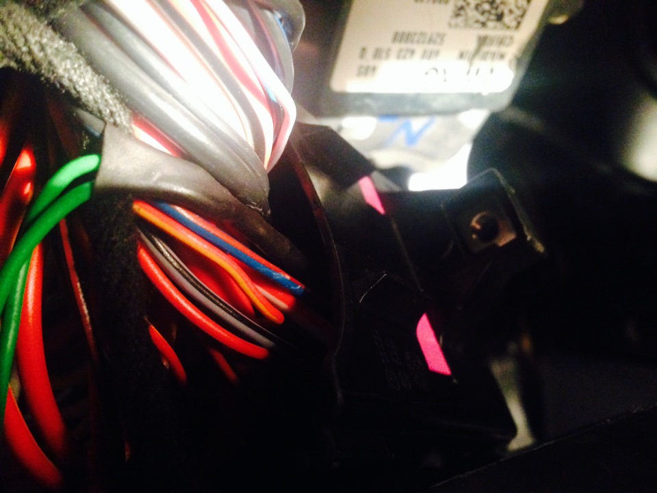
Here are the results of the above manipulations.
Now let's move on to installing the ESP button itself.
Its pinout: we hook
the 3rd pin to the 3rd pin of the seat heating key.
The 4th pin wire from this pin must be pulled into the engine compartment.
The 5th pin here we power the wire that was pulled from the 9th pre.
We hook the 6th pin to the 6th pin of the seat heating button.
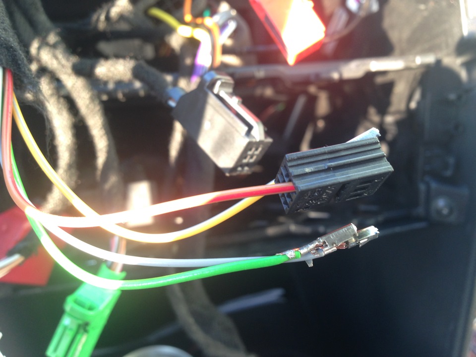
We connect the button.
Now we collect everything in the cabin in reverse order and go to the engine compartment.
Let's start by inserting a wire into the ABS / ESP block connector.
- Remove the connector from the block (remove the red flag (latch), raise the connector fixing bracket and pull it all the way forward).
- Remove the wiring harness connector cover.
- In order to have access to the contacts, you need to move the pink lock in the direction of the arrow.
- The wire must be inserted into the 22nd pin.
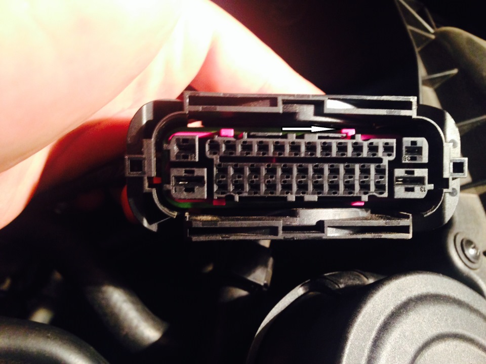
Block connector.
But the story doesn't end there! Since the connectors on machines with ESP are different, the socket we need is deaf! In order to be able to insert the pin, you need to take a 3.5 mm drill and CAREFULLY drill out the plastic.
Do it without fanaticism! Otherwise, the connector will become unusable!
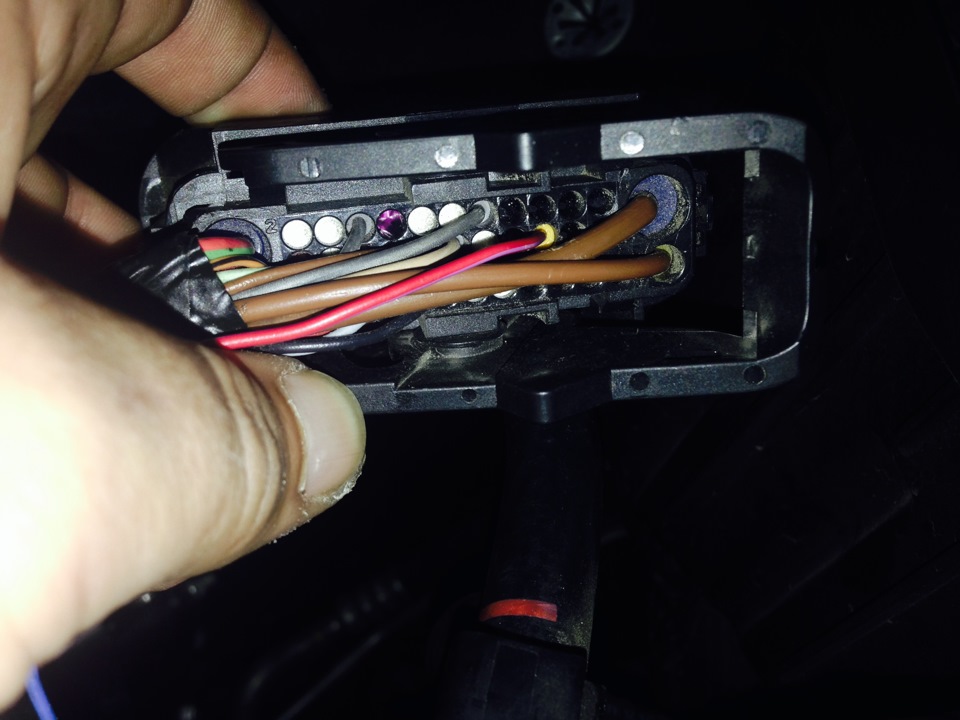
The wire took its place.
I PLEASE YOUR ATTENTION TO THE 22nd PIN WIRE IS INSERTED EXACTLY IN RUSSIAN POLO SINCE 2013 ON BLOCKS 9.0! IN EUROPEAN AND RUSSIAN UNTIL 2013 IT SHOULD BE IN THE 5TH PIN!
This completes the wiring part!

Required details.
We proceed to replace the block itself and the brake pipes:
- Unscrew the brake pipes from the GTZ, substitute the container so as not to fill the motorboat with brakes!
— Unscrew the brake pipes from the block.
- Raise the block up and pull it out.
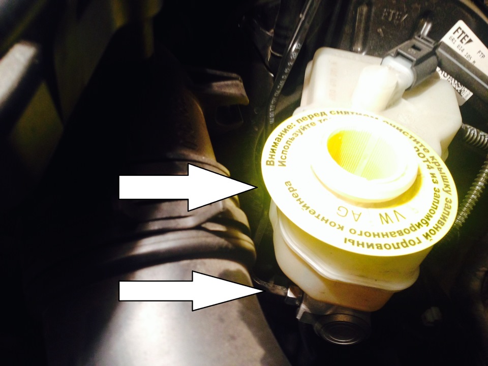
GTZ tube.
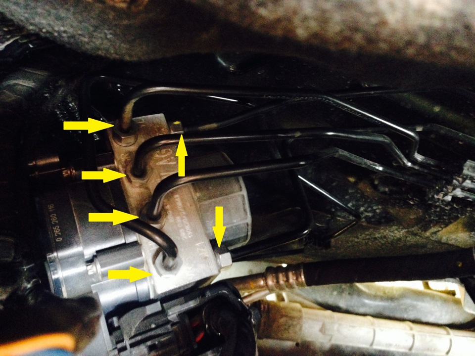
Next, dismantle the block bracket, it is fastened with 3 nuts.
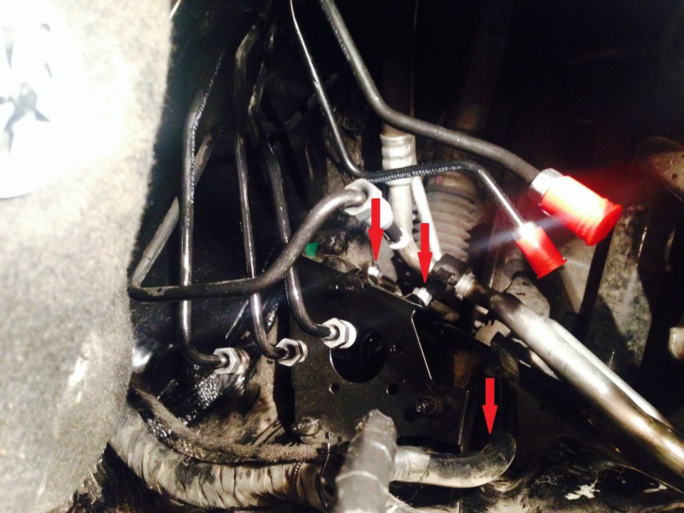
Old bracket.
- Install new tubes.
- Install new bracket.
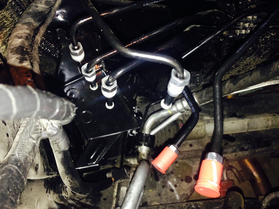
New bracket and new tubes.
Now we start pumping the system, namely, we initially pump the ABS / ESP unit, then we pump each brake circuit.
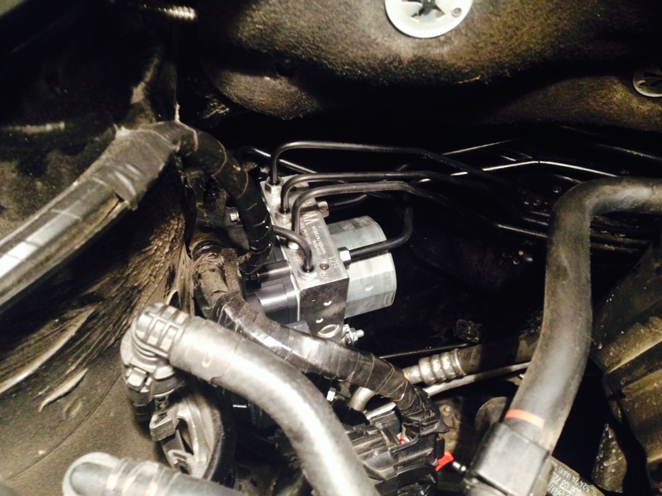
Here is the new unit installed and pumped.
This completes the mechanical part, let's move on to coding and adaptation! We take the string "VASYA", connect ...
We go to the 19th block / list of equipment / and put a checkmark in front of the 4th block / save.
Now the car sees under the steering ring with the angle sensor.
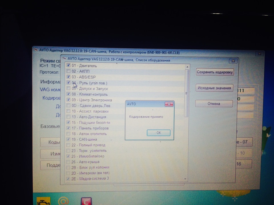
Steering wheel coding.
Now let's move on to coding the ABS / ESP block.
Here is an important point! For the new encoding, we need the encoding of the native ABS block!
From the native encoding, we need data of 5,7,9,11 and 13th bytes!
We just rewrite them.
Next, I took the donor's encoding, the cars already with the ABS / ESP block and added the data of my bytes!
Here is the encoding I got:
51DD2C6421 25 07 C4 8A 19 34 6A 84 59 E0401500
Those bytes that are from my machine are highlighted in bold.
We go to block 03 / long encoding / and enter the encoding / save.
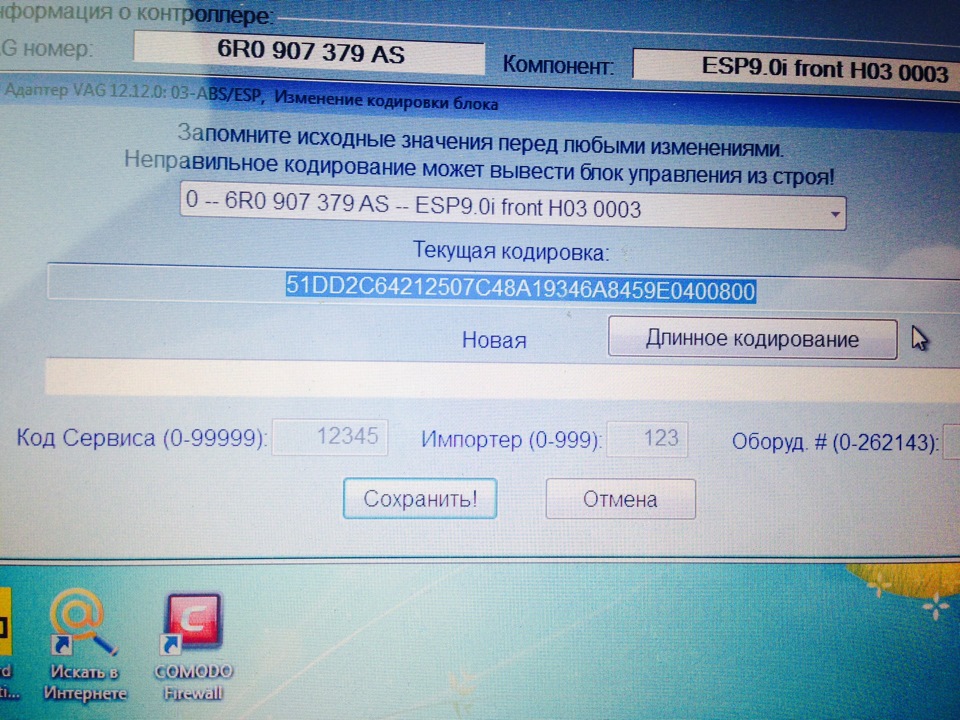
The block has accepted the encoding.
Next, go to "Basic Settings".
03 block/login/40168/save.
03 block/adaptation/channel adaptation/execute.
We turn off and turn on the ignition, after which three errors and enjoy the result.
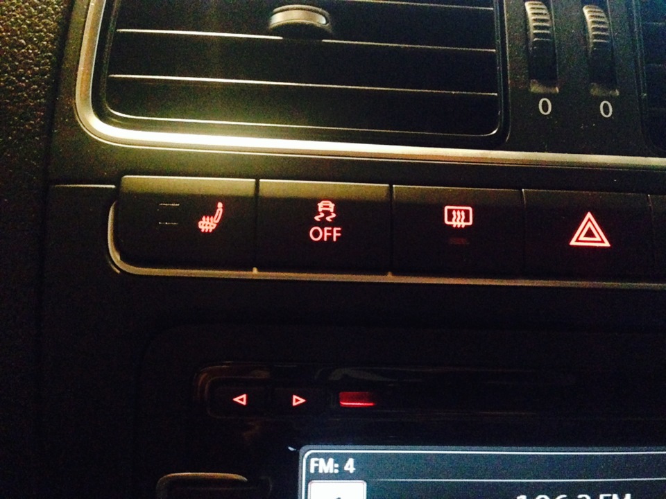
Button in place.
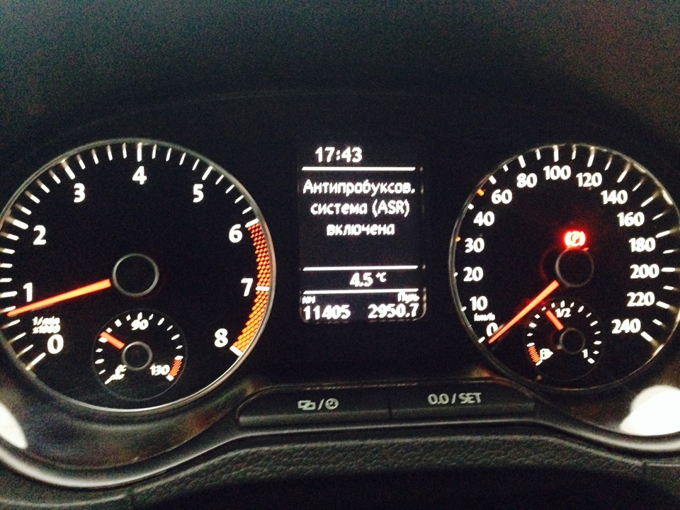
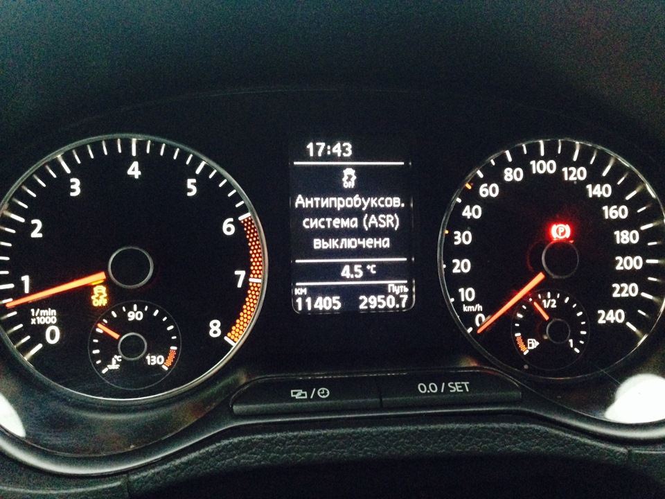
Working.
That's basically all the car started to ESPit!
Source: https://www.drive2.ru/l/4783762/
![4 generation [2001 - 2005]](/uploads/Volkswagen_Polo_2005_-_2009_.jpg)
![5 generation [2009 - 2015]](/uploads/Volkswagen_Polo_2009-2015_.jpg)
