![1 generation [1994 - 2006]](/uploads/Citroen_Jumpy_I_1994_-_2006_.jpg)

Tool:
- Straight spanner wrench 13 mm
- Collar for end nozzle
- Nozzle on the crank 13 mm
- torque wrench
- Finger №7014-TJ
- Pin No. 5711-T.A
- Pin No. 5711-T.V
- Pin #5711-TC
- Belt retaining clip Peugeot No.(-).0188-K.
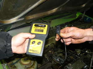
- SEEM C.TRONIC Belt Tension Meter
Parts and consumables:
- timing belt
Note:
Instructions for removing the timing belt can be found in this article .
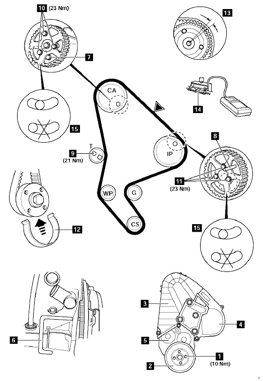
Timing belt installation diagram
1. Make sure that the flywheel fixing pin (6) and the lock (8) are in the correct position (hereinafter, see the timing belt installation diagram).
flywheel retainer
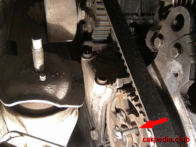
High pressure pump pulley fixing pin
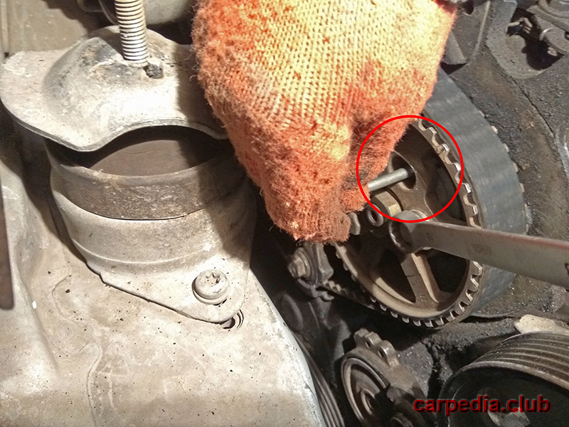
2. Make sure the camshaft pulley is locked with pin (7).
3. Loosen the camshaft pulley bolts (10). After that, tighten them tightly, and then loosen them 1/6 of a turn.
4. Turn the camshaft pulley clockwise until it stops against the pin (7).
5. Loosen the bolts (11) securing the high pressure fuel pump pulley. After that, tighten them tightly, and then loosen them 1/6 of a turn.
6. Turn the injection pump pulley clockwise until it stops against the pin (8).
Note:
The pulley can turn with little resistance.
7. Install the toothed belt on the crankshaft toothed pulley.
8. Install the belt retainer (12) around the crankshaft pulley.
9. Moving counterclockwise, start threading the belt through all the pulleys and rollers. Always check that the belt is taut between the pulleys.
10. Slightly rotating the injection pump pulley counterclockwise, we combine its teeth with the teeth of the belt.
11. In the same way, thread and install the belt on the camshaft pulley. Turn the pulley slightly counterclockwise to align its nearest teeth with the belt teeth.
Warning:
The rotation of the pulley is allowed no more than one tooth.
12. Pass the belt through the tension roller and through the water pump pulley.
13. Loosen idler bolt (9).
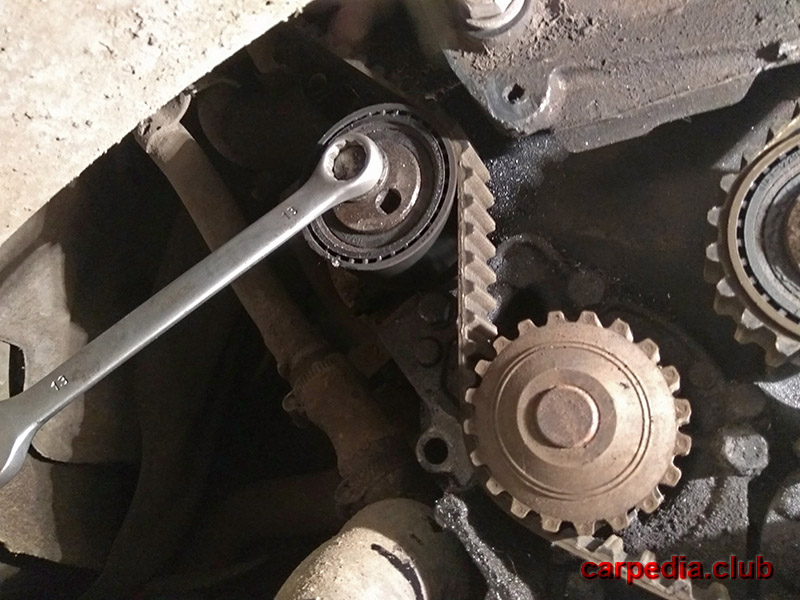
14. Turn the tensioner eccentric counterclockwise to temporarily tension the belt.
15. Lightly tighten the bolt (9) of the tension roller. Tightening torque 10 Nm.
16. Remove retaining clip (12).
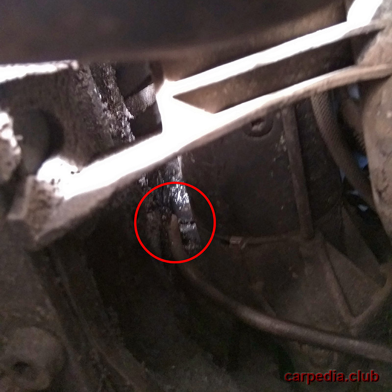
17. Install a belt tension gauge (14) at the point shown in the figure (between the camshaft pulley and the injection pump pulley).
Note:
Make sure that the sensor of the device does not touch the surrounding objects.
18. Rotate the idler eccentric counterclockwise until the tension meter reads 106 ± 2 SEEM units.
19. Tighten the bolt (9) of the tension roller to 18 Nm.
20. Remove the belt tension gauge (14).
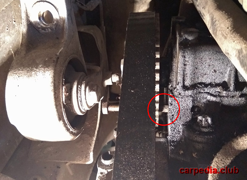
21. Make sure the locking pins are not at the end of the slotted holes (15) of the pulleys.
Note:
If the pulleys are not positioned correctly in relation to the locking pins, repeat the timing belt installation process.
22. Tighten the bolts for fastening the pulleys of the injection pump (11) and the camshaft (10) to a torque of 23-25 Nm.
23. Remove the flywheel fixing pin (6) and the high pressure fuel pump pulley (8).
24. Remove the timing pulley fixing pin (7).
25. Turn the crankshaft eight turns to the installation.
Warning:
Never turn the crankshaft counterclockwise.
26. Reinstall the flywheel fixing pin (6) and injection pump pulley pin (8).
27. Install the camshaft pulley fixing pin (7).
28. Loosen the bolts (10) securing the camshaft pulley.
29. Loosen the bolts (11) securing the high pressure fuel pump pulley.
30. Loosen the bolt (9) of the idler pulley.
31. Install the belt tension gauge (14) in the location shown in the figure.
32. Rotate the idler eccentric counterclockwise until the tension meter reads 42 ± 2 SEEM units.
33. Fix the tension roller in this position by tightening the bolt (9) to 18 Nm.
34. Tighten the camshaft pulley (10) and high pressure fuel pump pulley (11) bolts to 23-25 Nm.
35. Remove the belt tension gauge (14).
36. Remove the flywheel retainer (6) and the fixing pin of the injection pump pulley (8).
37. Remove the camshaft pulley fixing pin (7).
38. Turn the crankshaft two full turns clockwise to the installation position.
Warning:
Never turn the crankshaft counterclockwise.
39. Check belt tension. To do this, set the tension gauge (14) to the point indicated in the figure. It should correspond to the value of 38-51 SEEM units. If the obtained values do not meet the standard, repeat the above steps again.
40. Remove the belt tension gauge (14).
41. Remove the flywheel fixing pin (6) and the injection pump pulley retainer (8).
42. Remove the camshaft pulley fixing pin.
43. Turn the crankshaft two turns to the installation position.
44. Install locking pin (6) into flywheel.
45. Make sure the locking pin (7) can easily fit into the hole in the camshaft pulley.
46. Make sure that the locking pin (8) can easily fit into the hole in the high pressure fuel pump pulley.
47. Remove lock pin (6) from flywheel.
48. Install all parts in the reverse order of their removal, more here .
Note:
Tighten the crankshaft pulley screws to 10 Nm .
The article is missing:
- Tool photo
- Photo of parts and consumables
- High-quality repair photos
Source: carpedia.club