On a Lada Granta car with a VAZ-21126 engine, valve lifters (hydraulic lifters), made in the form of cylindrical pushers located between the camshaft and valves, combine two functions: transferring force from the camshaft to the valves and eliminating gaps in their drive.
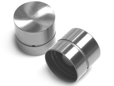
Valve lifters (hydraulic compensators)
The operation of the hydraulic compensator is based on the principle of incompressibility of engine oil, which constantly fills the internal cavity of the hydraulic pusher during engine operation and moves its plunger when a gap appears in the valve drive. Thus, constant contact of the valve lifter with the camshaft cam without play is ensured. This eliminates the need for valve adjustment during vehicle maintenance.
The principle of operation of the hydraulic compensator is shown in the figure:
The scheme of the hydraulic pusher in the valve mechanism of the VAZ 21126 engine:
a - the work of the hydraulic pusher at the time of opening the valve;
b - work of the hydraulic pusher at the moment of closing the valve;
1 - valve;
2 - check valve spring;
3 - check valve;
4 – a head of the block of cylinders;
5 - camshaft cam;
6 - pusher;
7 - plunger;
8 - plunger spring;
9 - sleeve;
10 - check valve body;
A, B - cavities of the hydraulic pusher;
B - oil channel.
Oil under pressure necessary for the operation of the hydraulic pusher is supplied to the internal cavities A and B from channel C of the engine lubrication system through a side hole in the pusher 6, made in the annular groove of its cylindrical surface. When the valve 1 is closed, the pusher 6 (through the plunger 7) and the sleeve 9 are pressed by the bursting force of the spring 8, respectively, to the camshaft cam 5 and the end of the valve stem. The pressure in cavities A and B is the same, the check valve 3 of the hydraulic pusher is pressed against the seat in the plunger 7 by the spring 2 - there are no gaps in the valve mechanism. When the camshaft rotates, the cam 5 runs on the pusher 6, moving it and the plunger 7 associated with it. The movement of the plunger 7 in the sleeve 9 leads to a sharp increase in pressure in the cavity B.
Despite small oil leaks through the gap between the plunger and the sleeve, the pusher 6 and the sleeve 9 move in one piece and open the valve 1. With further rotation of the camshaft, the cam 5 reduces the pressure on the pusher 6 and the oil pressure in cavity B becomes lower than in the cavity A. The check valve 3 opens and passes oil from cavity A, connected to the engine oil line, into cavity B. The pressure in cavity B increases, sleeve 9 and plunger 7, moving relative to each other, select a gap in the valve mechanism.
The pressure of the oil supplied to the hydraulic pushers is regulated by a valve installed in the cylinder head.
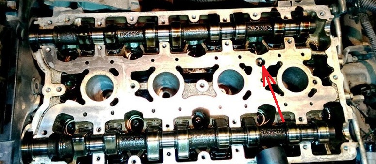
Placement of the anti-drainage valve of the oil channel in the cylinder head
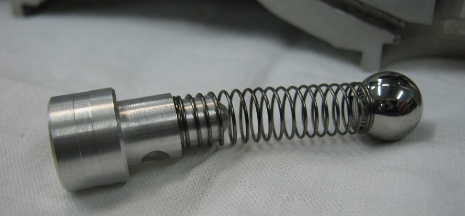
Cylinder head oil channel anti-drain valve
Since, after the engine is stopped, oil drains from the channels leading from the oil pump into the oil sump, and the channels for supplying oil to the hydraulic pushers remain filled, after starting the engine, air locks may form in the cavities of the latter. To eliminate them, calibration compensation holes are provided in the oil supply channels, which provide automatic purge of the cavities of the hydraulic pushers.
In addition, compensation holes make it possible to somewhat reduce the pressure of the oil entering the hydraulic pushers at a high engine speed, when the pressure in the cavity of the valve pusher can become so high that its pusher, leaning on the back of the camshaft cam, slightly opens the valve at a moment that does not correspond to gas distribution phase.
Almost all malfunctions of valve lifters are diagnosed by the characteristic noise emitted by the gas distribution mechanism in various engine operating modes. Knock from valves can sometimes be eliminated by slightly turning the spring or valve around the longitudinal axis. How to change faulty hydraulic lifters, see this article .
Source: carpedia.club
![1 generation [2011 - 2017]](/uploads/Lada_Granta_2011_-_2015.jpg)
