![1 generation [2003 - 2007]](/uploads/Mitsubishi_Outlander_I_2003_-_2008_.jpg)
![3 generation [2012 - 2014]](/uploads/3.png)
![XL [2005 - 2012]](/uploads/4d137205da66f_.jpg)
Tools:
- Screw jack
- Balloon wrench
- Medium flat screwdriver
- Phillips screwdriver medium
- Ratchet wrench
- Extension (with gimbal)
- 10 mm head
- 12 mm head
- Torque wrench
- Open-end spanner 10 mm
- 16 mm box spanner
- Pliers
- Marker
- Hexagonal special key for fixing the tensioning mechanism (or pin)
- Wheel chock (shoe)
- Knife (or scraper)
Parts and consumables:
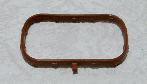
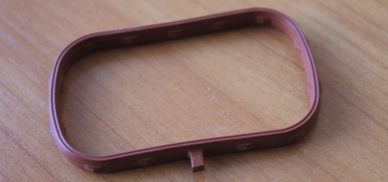
- Intake manifold gasket 1542A133 - 4 pcs.
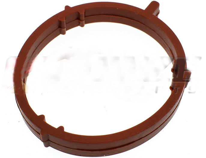
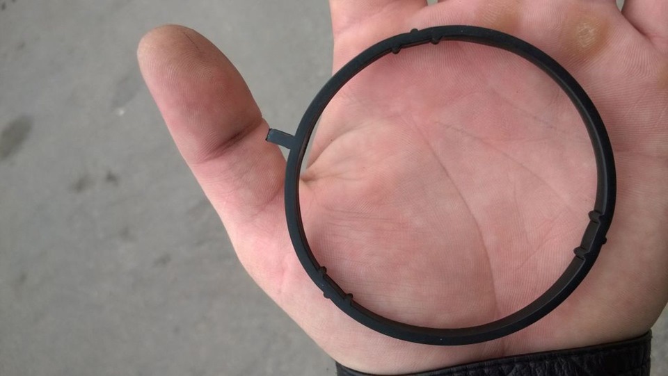
1542A134 Throttle Body O-Ring (If Required)

- Exhaust gas recirculation valve servo bracket O-ring 1542A048 (if necessary)
- Technical capacity
- Rope or wire
- Cleaner (or solvent)

- Hose
- Motor oil
- Coolant
- Rags
Note:
The intake manifold gasket is considered the most vulnerable point of this vehicle assembly. Therefore, it periodically requires its replacement, which is quite simple to do on your own.
Replacing the intake manifold gasket is necessary in such cases:
- when the engine is running, a characteristic whistle is heard;
- from under the hood you hear the sound of "suction" (experienced drivers immediately pay attention to it);
- uneven operation of the motor and the inability of the engine to reach full power;
- the engine is unstable at idle;
- there is a leak of engine oil or coolant (sometimes these phenomena are recorded simultaneously).
The work on replacing the intake manifold gasket for engines 4B12 and 4B11 is the same.
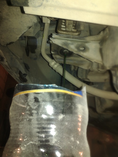
1. Drain the coolant as described here .
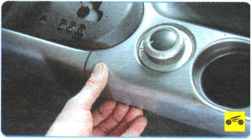
2. The Outlander HL engine is equipped with a decorative casing. To access the intake manifold, remove the shroud as described in this article .

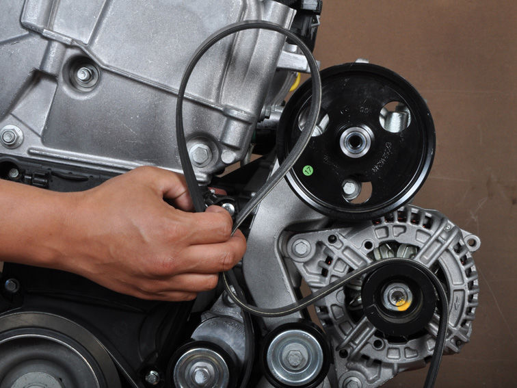
3. Remove the accessory drive belt as described here .
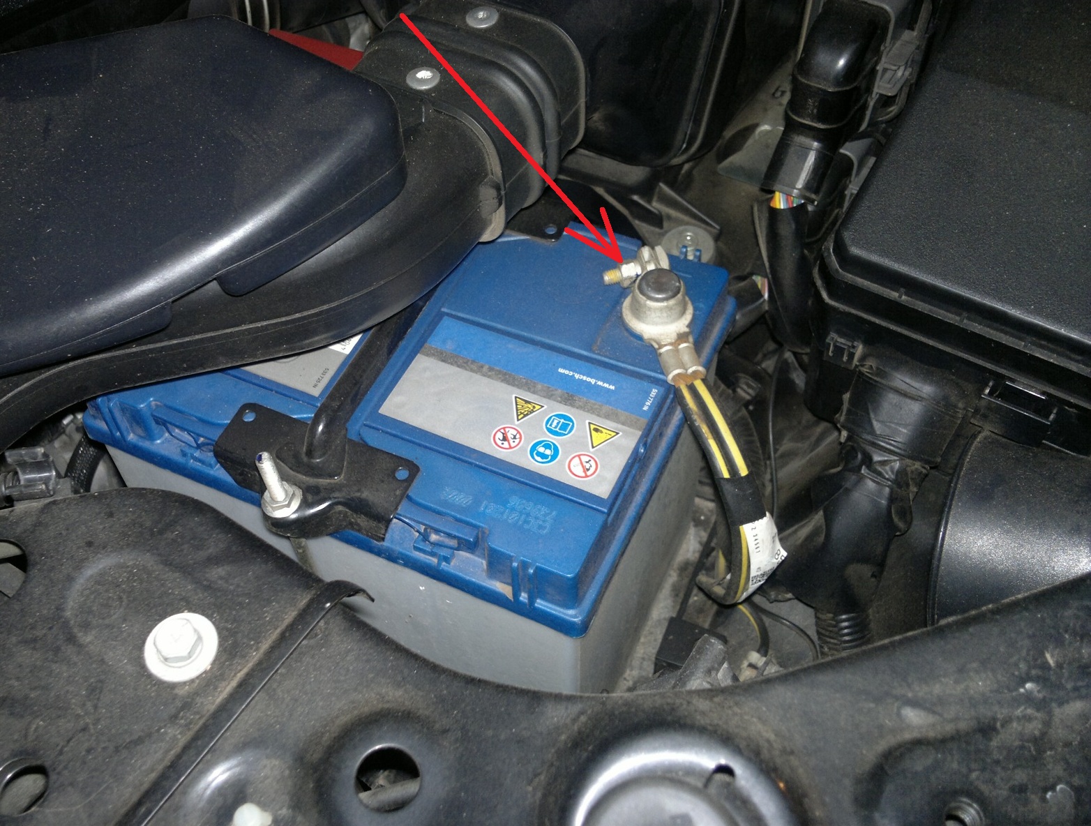
4. Disconnect the wire from the negative terminal of the storage battery.
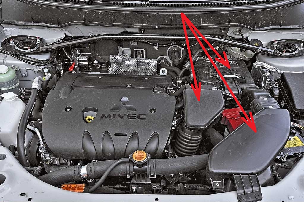
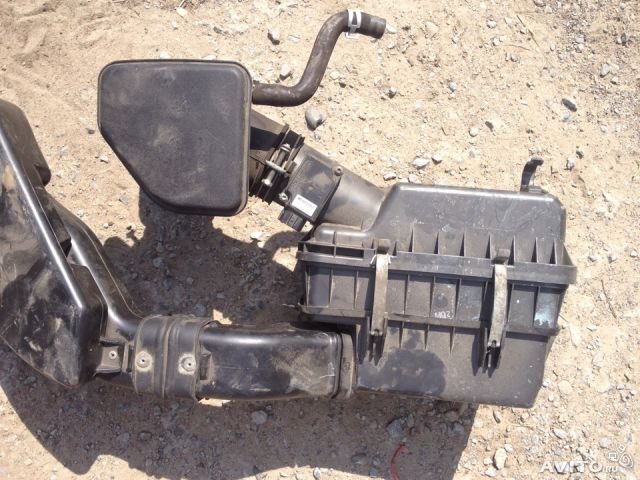
5. Remove the air filter assembly.
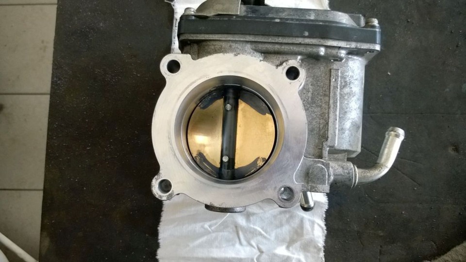
6. Remove the throttle body assembly and also remove the O-ring from the groove in the intake manifold flange.
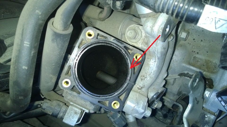
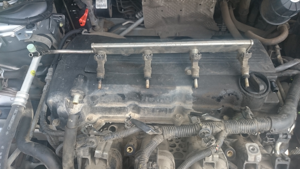
7. Remove the fuel manifold and injectors.
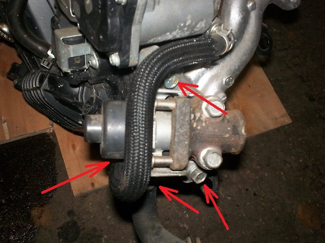
8. Remove the exhaust gas recirculation valve servo, the exhaust gas recirculation pipe and the servo bracket assembly.
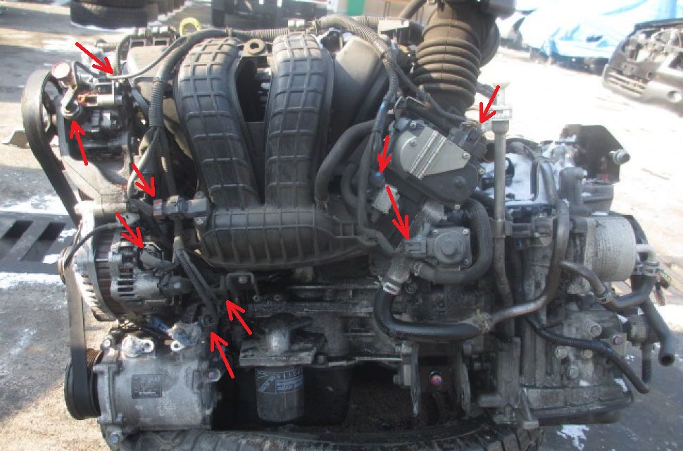
9. Disconnect the ECC harness connectors from the sensors to separate the ECM connector and harness retainer connections from the intake manifold.
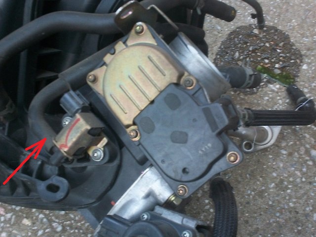
10. Remove the EVAP vacuum hose from the canister purge solenoid valve and remove the hose from the intake manifold.
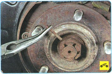
11. Using pliers, remove the brake booster vacuum hose from the intake manifold.
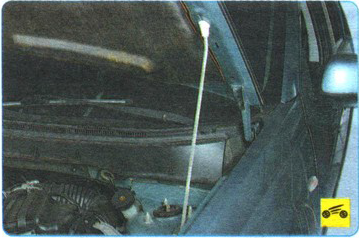
12. Remove the power steering pump from the bracket with the attached hoses.
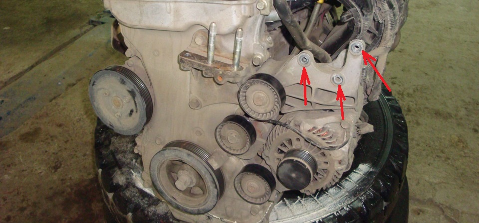
Note:
After removal, use a rope or wire to suspend the power steering pump assembly and hoses on the body in a location where they will not interfere with the removal of the intake manifold.
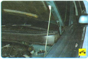
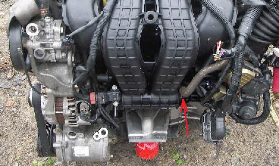
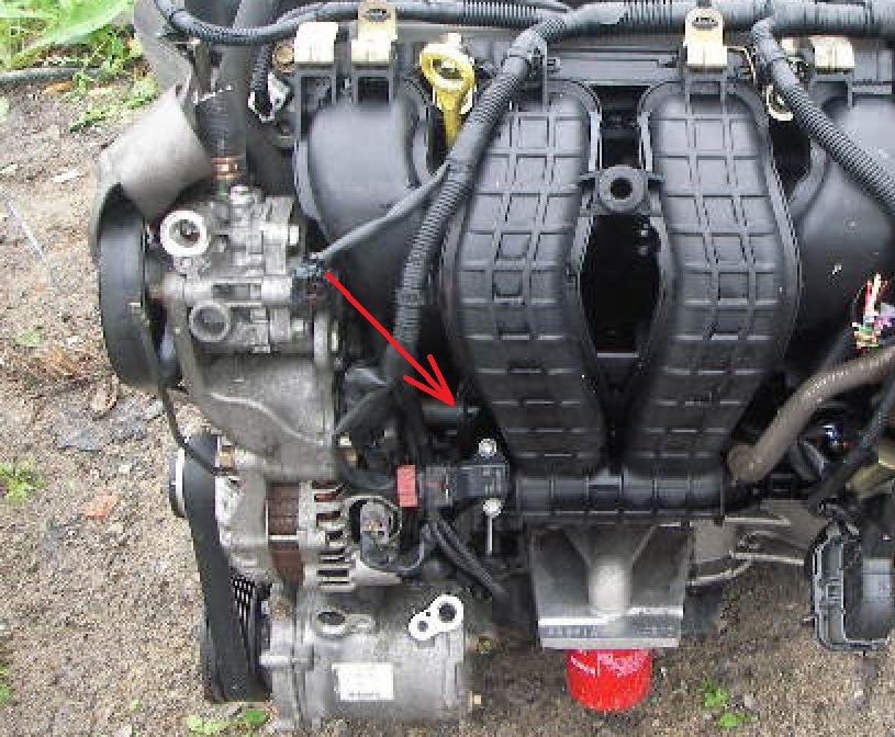
13. Then disconnect the positive crankcase ventilation hose from the intake manifold.
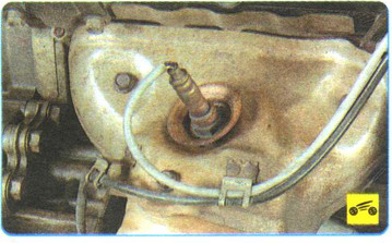
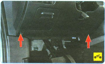
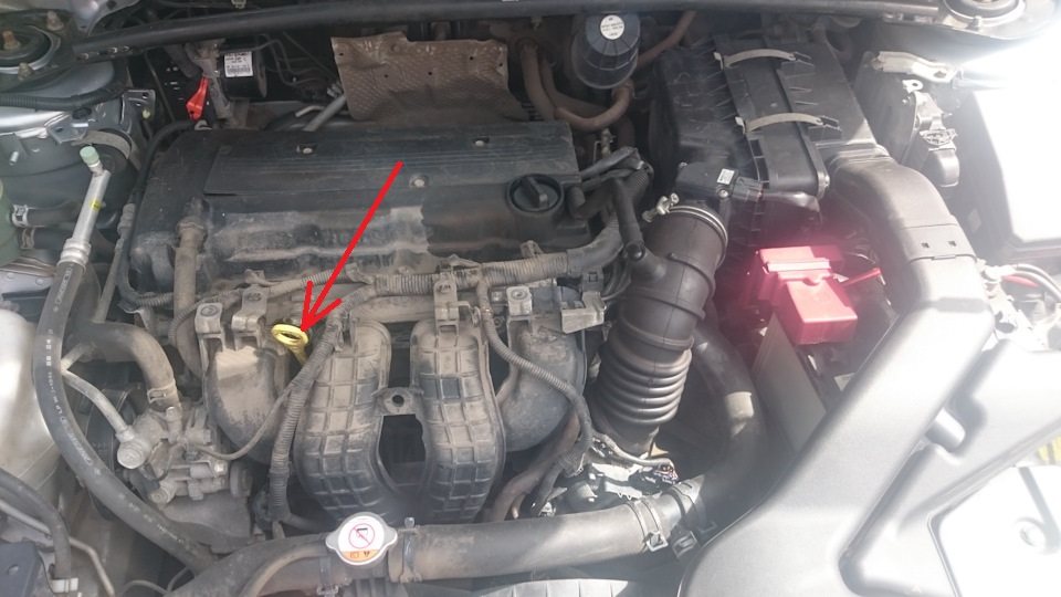
14. Remove the oil level indicator (dipstick).
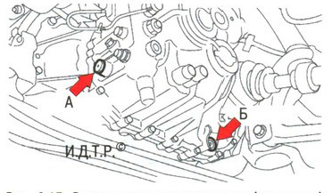
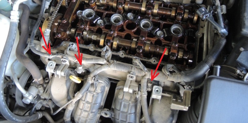
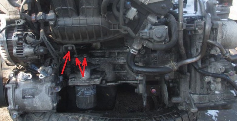
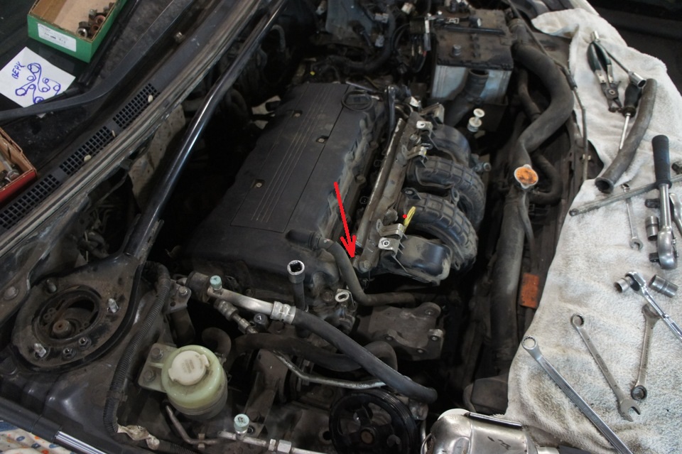
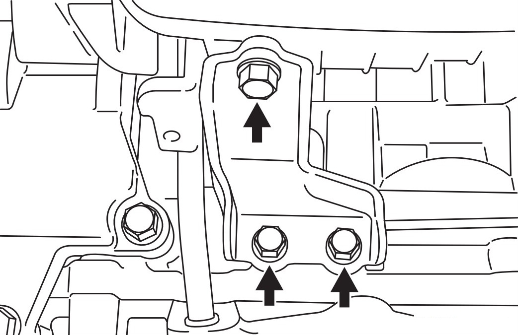
15. Remove the three bolts securing the intake manifold support and remove it.
16. Remove the left intake manifold bolt (the location of the bolt is shown with the intake manifold removed) and remove the front guard for the fuel injectors.
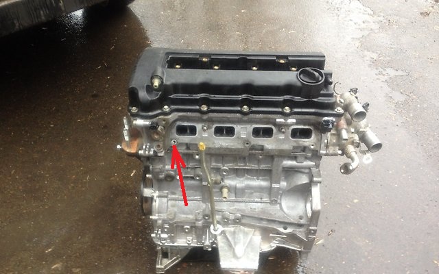
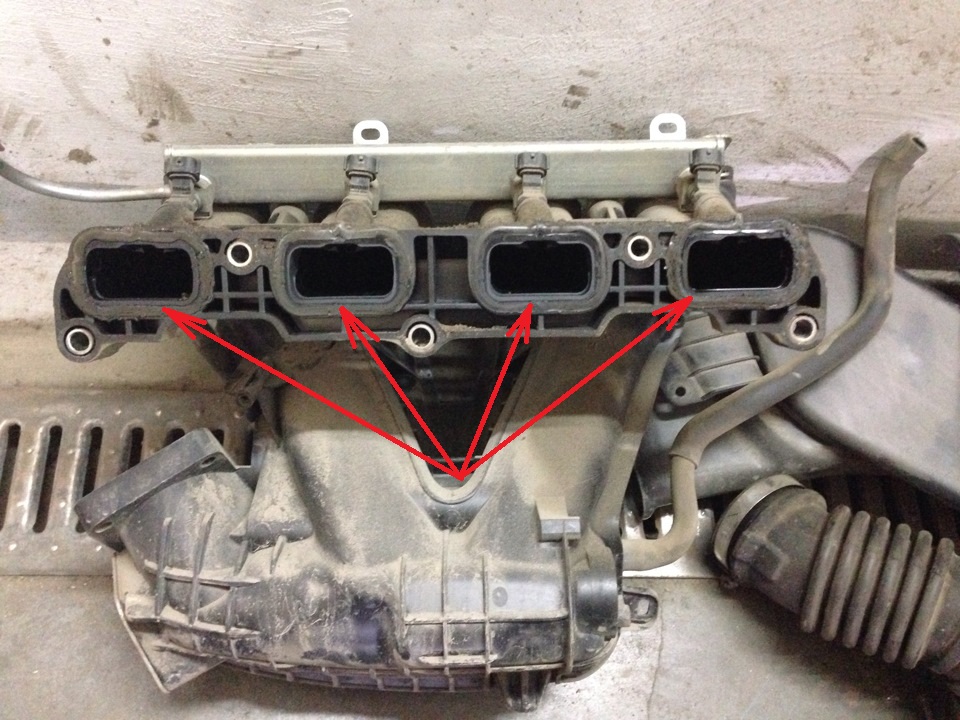
17. Remove the remaining nuts and bolts securing the intake manifold to the cylinder head and remove the intake manifold (on the removed manifold you can see the location of the holes for its fastening).
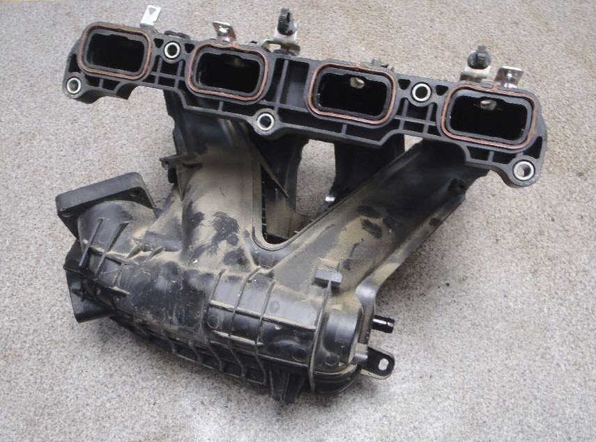
18. Remove the gaskets from the grooves of the intake manifold.
19. Install new intake manifold seals.
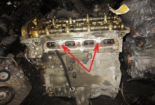
20. Clean the seating surface of the block head under the intake manifold from deposits.
21. Install the intake manifold assembly and the front injector guard, temporarily tighten the bolts and nuts.
Note:
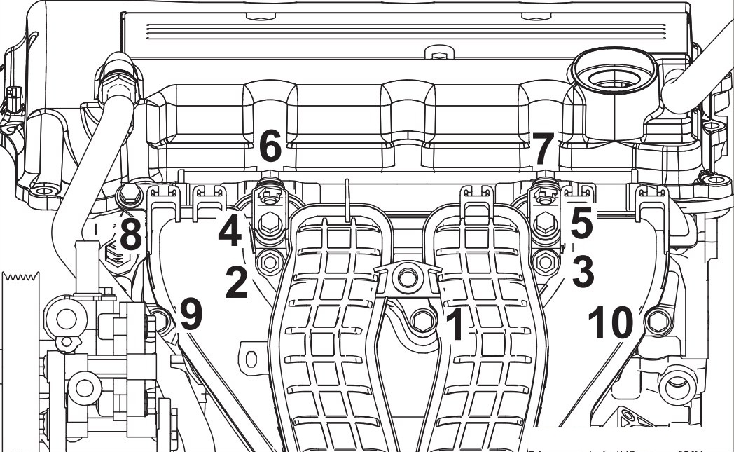
To avoid damage to the plastic intake manifold, tighten the fasteners of the fuel manifold, intake manifold assembly and injector guards in strict sequence.
22. Install the intake manifold support and hand-tighten the mounting bolts. Make sure the strut mating surface fits well to the intake manifold on one side and to the cylinder block on the other.
23. Tighten the mounting bolts with a nominal torque of 20 ± 2 N · m first from the side of the intake manifold and then from the side of the cylinder block.
Note:
Do not overtighten the mounting bolts as this may damage the bolt threads in the plastic intake manifold.
24. Then install all the removed parts in the reverse order of removal, and also fill the engine cooling system with coolant.

The article is missing:
- Tool photo
- Photos of parts and consumables
Source: carpedia.club